SS Hero Tie Fighter

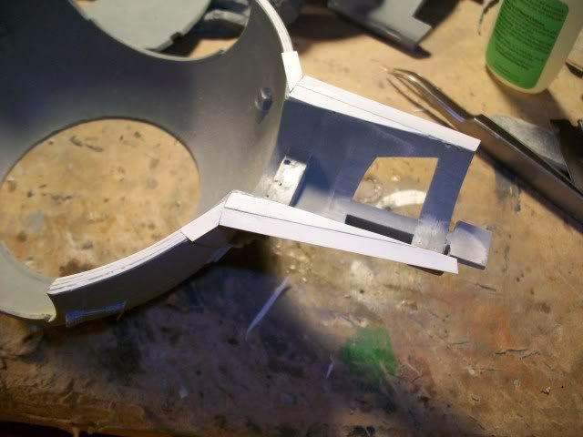
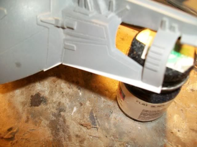
Not the same material on the damaged TIE wing. For that one they had to use a thinner backing so they could crumple it up a bit and make it all twisted etc... You can't do that with the art board. It's likely black construction paper in the "damaged" section of that TIE wing. The thinner paper would not be supportive enough to hold up the wing proper if that's all you used. This is only my theory. Peace,

Dave :)
 
QUESTION:

Would anyone be kind enough to measure the dimensions of said Plastruct "shapes" The 1/4" H column etc. The thickness of the various "faces" to such shapes. For instance, H-Column equals 1/4wide, 3/64 thick, top and bottom pieces separated by 3/16" etc??? Sorry to impose but if it is doable I would appreciate it.:cool
 
Nope, no seat in the kits. The back of the figure will be very very close to the armature, hence no room in there. If you used really thin styrene and only put the details on the outer edges where it wouldn't contact the pilot, you might sneak a custom chair in there.
 
I am finally seriously considering getting the TIE kit. Where does one get original Koolshade from? Has that been covered in other threads? I will also need all the Plastruct stuff, which I assume is from a website.
Any thoughts?

Thanks,
KK
 
Hi KK, I provided the original shade in a run mid-late last year to 15 or so folks. I kept a small section for myself, one remaining section is still in limbo, another is going to a trade and beyond that communication has been hit or miss with the contact I had tracked down in Georgia. There is some available from darth_myeek in the JY right now. If anyone else is still interested, I may be able to get a slight bit more, my contact had a handful of sections left but I had purchased most if it and it went into the hands of builders. Here's my e-mail if you want: acadiatech@adelphia.net

I am finally seriously considering getting the TIE kit. Where does one get original Koolshade from? Has that been covered in other threads? I will also need all the Plastruct stuff, which I assume is from a website.
Any thoughts?

Thanks,
KK
 
Last edited:
Hi KK, I provided the original shade in a run mid-late last year to 15 or so folks. I kept a small section for myself, one remaining section is still in limbo, another is going to a trade and beyond that communication has been hit or miss with the contact I had tracked down in Georgia. There is some available from darth_myeek in the JY right now. If anyone else is still interested, I may be able to get a slight bit more, my contact had a handful of sections left but I had purchased most if it and it went into the hands of builders. Here's my e-mail if you want: acadiatech@adelphia.net

DragnInk,
If you think it would help restore your line of communications I might be able to go knock on your contact's door. I'm outside of Atlanta myself.

FWIW???
 
Hi DD, that would be a great idea but I did get a response from him today. He had his cell phone deactivated and has a new number--maybe we can do a round 2 run if anyone is interested?? There was a handful that had to bail out late last summer/fall.

DragnInk,
If you think it would help restore your line of communications I might be able to go knock on your contact's door. I'm outside of Atlanta myself.

FWIW???
 
Last edited:
Since the cockpit ball halves join at would also be a scribed line I adjusted their size then added .010 strips slightly inset to depth from the edge so that once joined there is already a "panel line". Did the opposite on the rest of the joining areas so that those can just be sanded to a clean edge which helps avoid scribing over a joint or adding putty to re-contour after assembly.

000_0006-2.jpg

000_0005-2.jpg
 
Working on the cockpit ball I laid the armature in place which does have locating tabs to help set the diameter. The floor plate needs to be glued in at some pint so I first beveled it's edges for a uniform contact and then using the front canopy frame and rear fascia I adjusted the "width" with a large bar clamp until things fit nicely.


Now IMHO ILM/Lucas played a dirty lil trick on all of us by using what appear to be amber LEDs (or rod) for the exposed portion of the chin guns. But when they fire you see a green blast? Hmmmm, that's not fair. Since we'll have working guns I first cut the leads off of the kit supplied LEDs and then hogged out the inside to accept a mini bright green LED. When done, it looks amber but will light up green! Problem solved.


Last edited:
That is sweet DD.Skirting around the amber LED,awesome. I always love the lighted stuff but never do it myself,too lazy:unsure.Can't wait to see what you do inside. This guy is going to be happy I think. I don't know how you can send it away.
 
That is sweet DD.Skirting around the amber LED,awesome. I always love the lighted stuff but never do it myself,too lazy:unsure.Can't wait to see what you do inside. This guy is going to be happy I think. I don't know how you can send it away.


Thanks Fett! Um, well, when I send it away he sends me something in return. It works out!:)


For the rear I first drilled out and sleeved the openings to eliminate any light bleed.


Then to mount the red LEDs from behind I used successive sizes of telescoping tubing till the LED with ground off flange also fit within. Again, because I hate light leaks.
 
Looking great!!!

I was wondering, on the real models are the red led visible when off or are they set deep inside the tube and not visible unless lit? I really never researched but I'm planning to put some non functional red leds in there just for the looks. BTW what size red leds they should be?

GFollano

I "sleeved up" to get a 5mm behind it and it won't be too visible back inside the tube until turned on.

The stock casting will easily allow a 3mm with some room inside of it though? Now there's a size between those two (I forget which way the designations T1, T2, and T3 go?) which is probably 4mm (I don't seem to have one handy) which would probably snug right up inside it? HTH?
 
Using the locators on the cockpit floor and upper sphere I positioned the kit components for the cockpit and then filled in the sidewalls and some of the "roof". Next I'll "busy up" those sidewalls and then move to making a seat.

000_0002-5.jpg

000_0004-1.jpg

000_0001-3.jpg


I'll also address the bit of visible gaps when you look through the canopy and see it to the hull halves where the cockpit doesn't quite snuggle up against the opening.
 
In trying to get closer to what we see on those short glimpses inside the cockpit onscreen I'm making a few more changes.


I "found" or made an extra 1/4inch in depth for the cockpit. This was for visual effect and to better accommodate the pilot grasping the yet unmade control/flight yoke.
000_0001-4.jpg


And have started work on the pilot.
000_0003-1.jpg
 
Back
Top