You are using an out of date browser. It may not display this or other websites correctly.
You should upgrade or use an alternative browser.
You should upgrade or use an alternative browser.
Open Source Studio Scale TIE Fighter Thread
- Thread starter MrRobot
- Start date
-
- Tags
- opensource tie fighter
joberg
Legendary Member
Hallelujah BrotherYes, I agree! ABS is much better to work with than acrylic.
")
Build continues, albeit very slowly. Here's some pics of the nearly completed hatch. Not 100% happy with it. I was going for replicating some of the original asymmetry, but ended up with perhaps a bit too much asymmetry! I haven't done all the drill holes or attached the greeblies. I've got the Hetzer part and waiting on the 8rad part.
All in all, not bad for my first crack at a studio scale anything.


All in all, not bad for my first crack at a studio scale anything.
I have been working on the rear hatch lately. This is one part that has always perplexed me; I've never been quite sure how it was made. So, I looked at as many photos as I could, took some time to think about it, did a few trials and this is the method I have come up with.
There has been some discussion about whether the middle of the impressed part of the cone is flat or domed. I agree that it is subtly domed, based on what I've seen in pictures. However, this could always be chalked up to lens distortion.
The main proof came from these pictures of parts apparently out of the original molds from ANH. This is the only internal view of the rear hatch I have ever seen:

A few things jumped out at me. The first obviously being the concave surface.The second thing is the putty around the window, which appears to have been put in before the window was cut out. So I suspect this was a feature of the master and not some funky molding technique. But, hey, I could be very wrong. Finally, there's the really sharp brim to this piece. Not like any of the other hatches.
So here's my best interpretation of how this component was made.
I made a couple of cone bucks in Blender and 3D printed them to make a vacuum-forming buck (I can give you my STLs if you want). The following series of images are not really chronological and reflect a few different attempts at this.

Then I trimmed out the cone with a height gauge:

This would form the outer cone, which I then welded down to a dome that I vacuum-formed over my 5.25" hemidomes:

To make the inner concavity, I felt from looking at images this surface may have been a bit concave, rather than conic, so I formed some 1.5mm styrene over a 2.75" hemisphere, then cut and sanded it down to the "right" diameters.


This all fits together near-perfectly:

Add another dome over the middle and the rosette of chips:

I think the chips should taper inwards a bit; mine are probably a bit too parallel-sided. If I had thought it through a bit better, I would have formed them over the 2.75" hemisphere, too (perhaps immediately over the 1.5 mm pull). But here we are.
And here's the near-finished product:


Far from perfect, but happy enough with the result for now. I've learned a good few things that I would do differently if I were to do it all again. Overall, the process seems to work, but did require a good bit of puttying and sanding at the contact between the outer cone and the underlying dome. I don't want to do it again, but now when I look at it all I see are the imperfections!
And, of course, in a nod to the original, I puttied the back:

Not really functional in my case, but does thicken out the window frame a bit, so why not.
There has been some discussion about whether the middle of the impressed part of the cone is flat or domed. I agree that it is subtly domed, based on what I've seen in pictures. However, this could always be chalked up to lens distortion.
The main proof came from these pictures of parts apparently out of the original molds from ANH. This is the only internal view of the rear hatch I have ever seen:
A few things jumped out at me. The first obviously being the concave surface.The second thing is the putty around the window, which appears to have been put in before the window was cut out. So I suspect this was a feature of the master and not some funky molding technique. But, hey, I could be very wrong. Finally, there's the really sharp brim to this piece. Not like any of the other hatches.
So here's my best interpretation of how this component was made.
I made a couple of cone bucks in Blender and 3D printed them to make a vacuum-forming buck (I can give you my STLs if you want). The following series of images are not really chronological and reflect a few different attempts at this.
Then I trimmed out the cone with a height gauge:
This would form the outer cone, which I then welded down to a dome that I vacuum-formed over my 5.25" hemidomes:
To make the inner concavity, I felt from looking at images this surface may have been a bit concave, rather than conic, so I formed some 1.5mm styrene over a 2.75" hemisphere, then cut and sanded it down to the "right" diameters.
This all fits together near-perfectly:
Add another dome over the middle and the rosette of chips:
I think the chips should taper inwards a bit; mine are probably a bit too parallel-sided. If I had thought it through a bit better, I would have formed them over the 2.75" hemisphere, too (perhaps immediately over the 1.5 mm pull). But here we are.
And here's the near-finished product:
Far from perfect, but happy enough with the result for now. I've learned a good few things that I would do differently if I were to do it all again. Overall, the process seems to work, but did require a good bit of puttying and sanding at the contact between the outer cone and the underlying dome. I don't want to do it again, but now when I look at it all I see are the imperfections!
And, of course, in a nod to the original, I puttied the back:
Not really functional in my case, but does thicken out the window frame a bit, so why not.
joberg
Legendary Member
Your eyeballs are working perfectly for sureWhen you realise your scratch-built part is, in fact, a kit part. Got pretty close by eyeballing it!
View attachment 1919737
Fujimi Iowa now added to the rear hatch map.
Shamon
Member
Tiger II (King Tiger) Fujimi 1/76I've now got a 1/72 kit and it appears to be too big. For reference, here it is against the Sherman part.
View attachment 1900324
So, it looks like it will need to be the 1/76 Tiger—if it's that at all!
Attachments
Thanks Shamon! The size looks almost right, but I fear the details of that part are not quite right. The four fastening bolts look a bit too small:Tiger II (King Tiger) Fujimi 1/76
I think this is something other than a Tiger II part.
DAR23
Member
This past weekend I started reviewing the maps and cataloging the kit parts I have.
I've noticed a couple of errors in the maps, in case you'd like to correct them. In the image TIE-parts-01.png, I’d say that #30 belongs to the Hurricane and not the P-51D. Also, one of the five parts of the Harrow is labeled as #10 when it should be #9.
Next I'll check the Wingstars.
I've noticed a couple of errors in the maps, in case you'd like to correct them. In the image TIE-parts-01.png, I’d say that #30 belongs to the Hurricane and not the P-51D. Also, one of the five parts of the Harrow is labeled as #10 when it should be #9.
Next I'll check the Wingstars.
Thanks for this!
Just a heads-up: I have a few updates to the maps which I've not yet posted. I'll do that over the weekend. Most of the recent progress has been on the wingstar struts, but I have a lot of uncertainty. So, I'll be very keen to get another opinion.
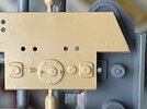
For part #30 on the wingstar hub, I'm reasonably sure that's the P-51D, not the Hurricane. The parts are indeed almost indistinguishable, but the P-51D has a little post on the top of one of the ignition heads that doesn't occur in the Hurricane ones:
Here's the P-51 part arrow pointing to the post:

Here's two sides of the Hurricane part:


No post.
And here's the TIE showing the post:

Nevertheless, I remain open to other views/info. I suppose it's entirely possible that there were tooling changes to the Hurricane that aren't widely known. Of course, with a bit of modification, the Hurricane part would likely do as a reasonable substitute if you don't want to splash out for a P-51!
Thanks for catching the mis-numbering of the Harrow part! I've just updated that in my local file. Will include it in this weekend's updates here.
Just a heads-up: I have a few updates to the maps which I've not yet posted. I'll do that over the weekend. Most of the recent progress has been on the wingstar struts, but I have a lot of uncertainty. So, I'll be very keen to get another opinion.
For part #30 on the wingstar hub, I'm reasonably sure that's the P-51D, not the Hurricane. The parts are indeed almost indistinguishable, but the P-51D has a little post on the top of one of the ignition heads that doesn't occur in the Hurricane ones:
Here's the P-51 part arrow pointing to the post:
Here's two sides of the Hurricane part:
No post.
And here's the TIE showing the post:
Nevertheless, I remain open to other views/info. I suppose it's entirely possible that there were tooling changes to the Hurricane that aren't widely known. Of course, with a bit of modification, the Hurricane part would likely do as a reasonable substitute if you don't want to splash out for a P-51!
Thanks for catching the mis-numbering of the Harrow part! I've just updated that in my local file. Will include it in this weekend's updates here.
DAR23
Member
Thanks for this!
Just a heads-up: I have a few updates to the maps which I've not yet posted. I'll do that over the weekend. Most of the recent progress has been on the wingstar struts, but I have a lot of uncertainty. So, I'll be very keen to get another opinion.
For part #30 on the wingstar hub, I'm reasonably sure that's the P-51D, not the Hurricane. The parts are indeed almost indistinguishable, but the P-51D has a little post on the top of one of the ignition heads that doesn't occur in the Hurricane ones:
Here's the P-51 part arrow pointing to the post:
View attachment 1934670
Here's two sides of the Hurricane part:
View attachment 1934671View attachment 1934672
No post.
And here's the TIE showing the post:
View attachment 1934673
Nevertheless, I remain open to other views/info. I suppose it's entirely possible that there were tooling changes to the Hurricane that aren't widely known. Of course, with a bit of modification, the Hurricane part would likely do as a reasonable substitute if you don't want to splash out for a P-51!
Thanks for catching the mis-numbering of the Harrow part! I've just updated that in my local file. Will include it in this weekend's updates here.
Ahh you are right!! I forgot to check the pics from the auction, it's crystal clear now. This is good news because I already have the P-51D.
BTW, maybe you already found it, but do you see anything familiar in this picture?
Yep. Found it. That very pic was the one that clued me in! I've got the kit and can send you greebly casts this summer.Ahh you are right!! I forgot to check the pics from the auction, it's crystal clear now. This is good news because I already have the P-51D.
BTW, maybe you already found it, but do you see anything familiar in this picture?
View attachment 1934714
DAR23
Member
I won’t need this kit as it's already on the way, but yes we’ll talk in the summer about the others I may needYep. Found it. That very pic was the one that clued me in! I've got the kit and can send you greebly casts this summer.
. Thanks!
joberg
Legendary Member
The pic with the arrow pointing to the part seems higher and thinner than the one on the original model (seems to me that it's lower and stubier). Maybe it was a piece added by one of the modeler at the timeThanks for this!
Just a heads-up: I have a few updates to the maps which I've not yet posted. I'll do that over the weekend. Most of the recent progress has been on the wingstar struts, but I have a lot of uncertainty. So, I'll be very keen to get another opinion.
For part #30 on the wingstar hub, I'm reasonably sure that's the P-51D, not the Hurricane. The parts are indeed almost indistinguishable, but the P-51D has a little post on the top of one of the ignition heads that doesn't occur in the Hurricane ones:
Here's the P-51 part arrow pointing to the post:
View attachment 1934670
Here's two sides of the Hurricane part:
View attachment 1934671View attachment 1934672
No post.
And here's the TIE showing the post:
View attachment 1934673
Nevertheless, I remain open to other views/info. I suppose it's entirely possible that there were tooling changes to the Hurricane that aren't widely known. Of course, with a bit of modification, the Hurricane part would likely do as a reasonable substitute if you don't want to splash out for a P-51!
Thanks for catching the mis-numbering of the Harrow part! I've just updated that in my local file. Will include it in this weekend's updates here.
The pic with the arrow pointing to the part seems higher and thinner than the one on the original model (seems to me that it's lower and stubier). Maybe it was a piece added by one of the modeler at the time
It's likely shorter because it was either sanded down or partly obstructed by an air pocket in the mold during casting. TIE wings are replete with casting bubbles. In some models, the only evidence of the post is a circular "scar" from the base of a bubble. For instance, that's what you see in the image used in the parts map.
Looking at the photos, I don't see that the post is thicker. The base is pretty much the same width as far as I can tell. In both images, the base of the post fits tightly between the outer margin of the part and the sharp ridge that runs transversely across the part. It's possible that the post has a bit of a taper, causing it to look thinner (the part that stands proud admittedly has better contrast than the base in the kit scan photo).ok but how would that make the post THICKER?
Similar threads
- Replies
- 114
- Views
- 11,505
- Replies
- 5
- Views
- 743