xl97
Master Member
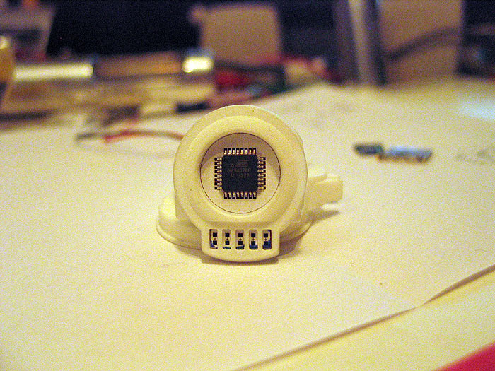
got my shooter (singular) today..... (finally!) ")
already made some headway on the PCB design...
confirmed a no sound pcb would be easy/doable..... and would only need the input of how/what you guys want use for switches.. I can put two generic 'pads' somewhere and you can solder whatever you like.. or we can think of some custom solution..etc
re: audio..
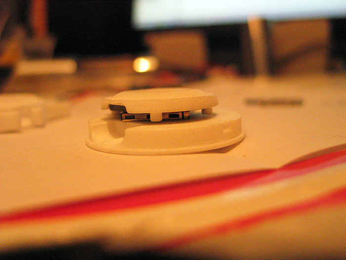
I rotated the uSD socket a bit.. to make it not interfere with the 'post'.. (they are quite the pain!... well only because this a retro fit though)
I have bee playing with the idea of only using 2 of the posts.. and cutting the other two off.. so I dont have to make drill holes in the PCB to accommodate for them.. and hence have a bit more space....thoughts?
this is a FUN challenge for me!.. I think we're close!..
***NOTE: need some help in brain-storming here guys..
since there is nothing on TOP of the PCB.. (except the main 'chip'.. and the LEDs)...
there is no room to mount any 'red' leds to light up the MAIN chip/red bingo chip....
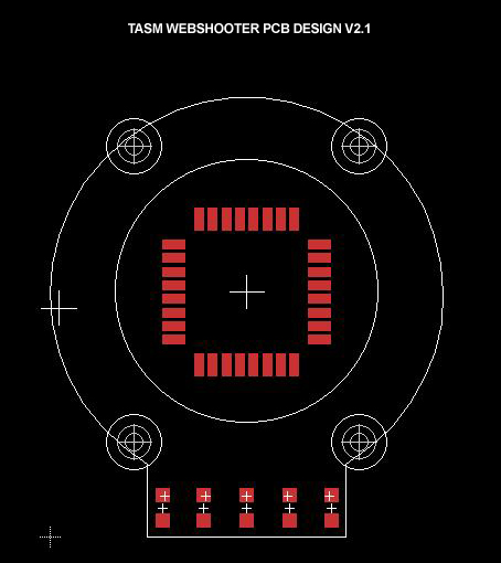
**Status of current PCB design:
schematic layout is 80% done.. (changing as we go along to accommodate for pads/led..etc)
pcb design is about 70% complete..
drill holes and layout figured out..
ID/OD of the model (and hence pcb size) figured out.
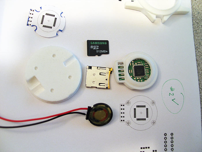
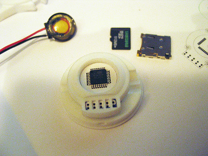
test prints of pcb size and led alignment and chip position = done/good!
(top)
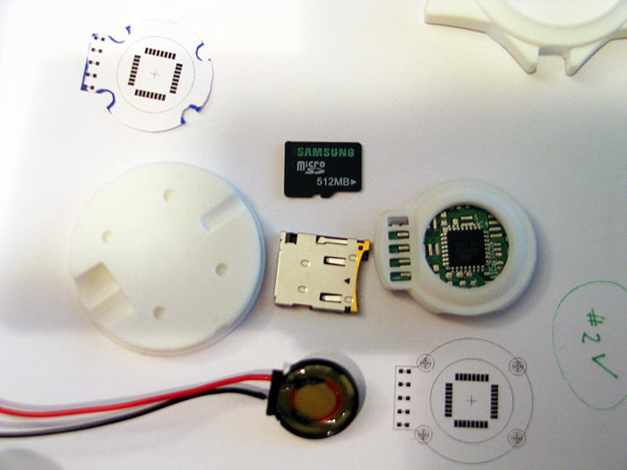
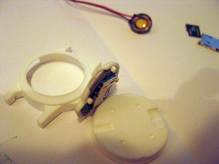
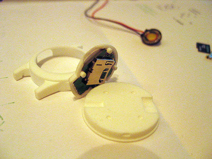
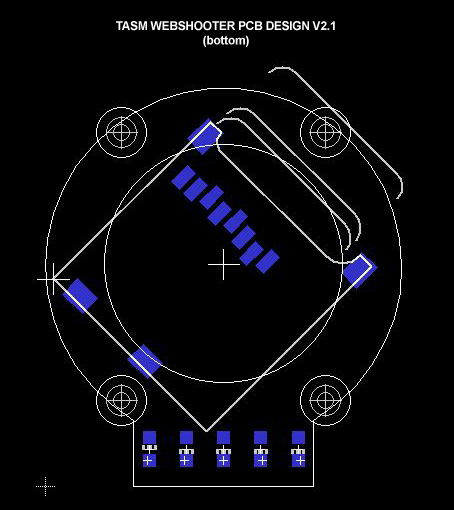
(bottom) - gives better idea of size/angle of the SD card and space when inserted and ejected..etc
things let to 'hash out'
1.) power input pads
2.) final placement of components (caps/resistors)
3.) give thought to how to flash bootload (pre-flashed? on-board ICSP pads?)
4.) give thought to how to upload sketches after assembly/future (on-board serial pads?)
5.) discuss how to we want to go about illuminating the top 'red' center?
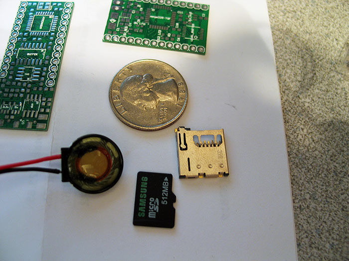
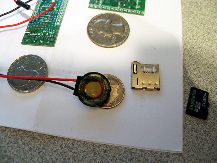
when I get home form work.. I'll post some pics of the print outs.. the speaker I found..uSD socket..etc..
so e can have a visual on how things we come together..
thanks!
already made some headway on the PCB design...
confirmed a no sound pcb would be easy/doable..... and would only need the input of how/what you guys want use for switches.. I can put two generic 'pads' somewhere and you can solder whatever you like.. or we can think of some custom solution..etc
re: audio..
I rotated the uSD socket a bit.. to make it not interfere with the 'post'.. (they are quite the pain!... well only because this a retro fit though)
I have bee playing with the idea of only using 2 of the posts.. and cutting the other two off.. so I dont have to make drill holes in the PCB to accommodate for them.. and hence have a bit more space....thoughts?
this is a FUN challenge for me!.. I think we're close!..
***NOTE: need some help in brain-storming here guys..
since there is nothing on TOP of the PCB.. (except the main 'chip'.. and the LEDs)...
there is no room to mount any 'red' leds to light up the MAIN chip/red bingo chip....
**Status of current PCB design:
schematic layout is 80% done.. (changing as we go along to accommodate for pads/led..etc)
pcb design is about 70% complete..
drill holes and layout figured out..
ID/OD of the model (and hence pcb size) figured out.
test prints of pcb size and led alignment and chip position = done/good!
(top)
(bottom) - gives better idea of size/angle of the SD card and space when inserted and ejected..etc
things let to 'hash out'
1.) power input pads
2.) final placement of components (caps/resistors)
3.) give thought to how to flash bootload (pre-flashed? on-board ICSP pads?)
4.) give thought to how to upload sketches after assembly/future (on-board serial pads?)
5.) discuss how to we want to go about illuminating the top 'red' center?
when I get home form work.. I'll post some pics of the print outs.. the speaker I found..uSD socket..etc..
so e can have a visual on how things we come together..
thanks!