Spiderman web shooter: A collaborative project.

Re: Spiderman web shooter: A collaborative project. Now with wiring diagrams!

I can do it on my work computer.. :)

(stinks for tonight though.. was ready to put in a few hours) lol

(I suppose I can watch Walking Dead though now) :)


Good for 20 saves?..so if I never save anything.. Im ok to open things forever? haha..

I dont know the first thing about it..(hope I dont get overwhelmed with all the interface/GUI controls?)

easy to grab a model/file and get dimensions? and move it around?


other things to note.. I just checked out..

we can get read or blue PCB's for only $5.00 more bucks..

and 0.0393701 " thick PCBs for same price..

(thickness)
.8mm - $2.00 more
.6mm - $10.00 more
.4mm - $25.00 more

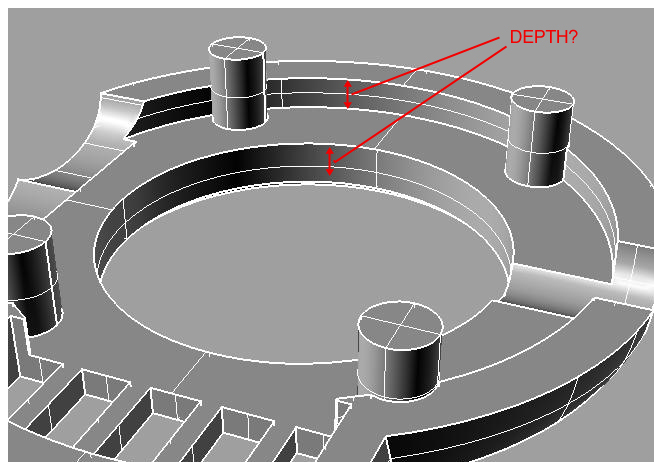
using a thinned pcb may help since we have limited room.. (especially depth)


(this is also for a 'batch' of 9-10 pcbs though too)

I think red would be good for this project.. :)

can do 'real' time web shooter.. fwwwip sound.. and take away from the led bargraph after xx amount of presses..

have to reload.....

random quotes from the movie..


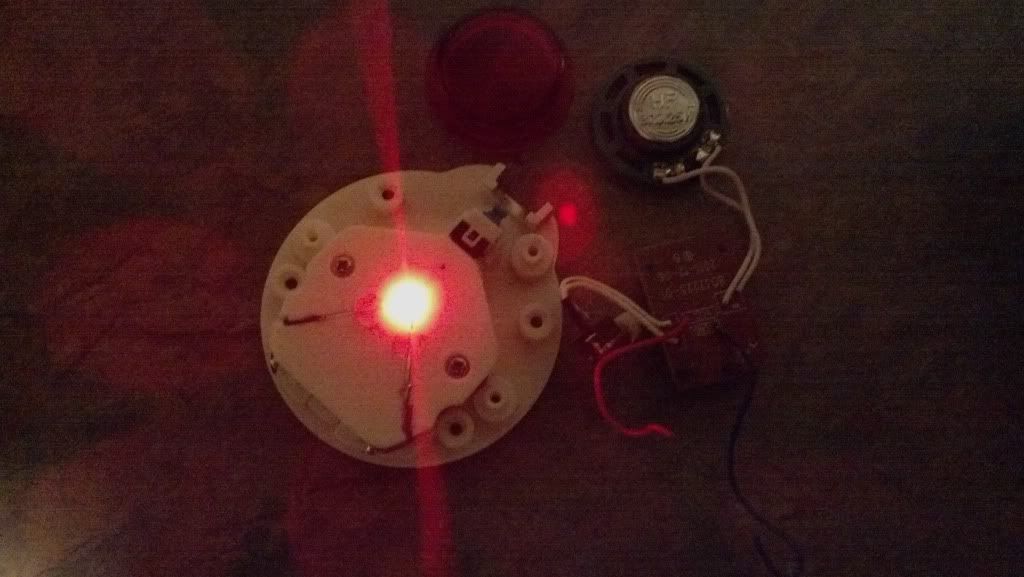
damn... (I totally forgot about a speaker!!!!!!)

grrr.. (too excited about this project, need to slow down I guess) lol


edit:

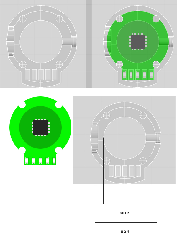
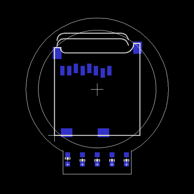
I just added the micro SD socket footprint to the layout.. and Im pretty confident now that there will be NO SOUND for these on the stock/default/current models..

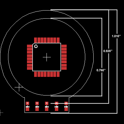
the micro SD socket is pretty big compared to the inner circle (bingo chip hole Im calling it)..

(.75 in ID..until Im told different)..

as it will bump into the legs/posts on the bezel piece


**** maybe if I can rotate it a bit to fit inside of the posts?

a no sound version is 100% possible I think..
 
Last edited:
Re: Spiderman web shooter: A collaborative project. Now with wiring diagrams!

Heres some pics Of my progress will hopefully have my watch soon
2012-11-17_20-07-49_737_zps4989fe1f.jpg
 
Last edited:
Re: Spiderman web shooter: A collaborative project. Now with wiring diagrams!

guys,everybody wat if we set up a new thread were we can all come up with ideas on how to make a real web shooter????
 
Re: Spiderman web shooter: A collaborative project. Now with wiring diagrams!

guys,everybody wat if we set up a new thread were we can all come up with ideas on how to make a real web shooter????

That might be better suited for a science and engineering forum.
 
Re: Spiderman web shooter: A collaborative project. Now with wiring diagrams!

Here is my work so far. Gonna rework the designs, make the base a bit wider and the dome part a bit taller than what i got from the 3d prints and i have began sculpting a wider/thicker nozzle. Opted to make the watch frame myself as the other one seemed a bit too bulky. Will be doing work on the watch frame also once i pick up more silicon. Have to add the little notches on either side of the nozzle and the number plates for 12,3,6,9.
I made a larger cartridge to make it more screen accurate from the screen grabs i have and have it held in with a 5mm disc magnet.
 
Re: Spiderman web shooter: A collaborative project. Now with wiring diagrams!

guys,everybody wat if we set up a new thread were we can all come up with ideas on how to make a real web shooter????

Read, digest, and take fellow members advice. It just may be helpful :)

That might be better suited for a science and engineering forum.

There are a few websites that you can see the discussion of this very topic in great detail. Search "real web shooter" on Google, and the explore first few results. :)
 
Re: Spiderman web shooter: A collaborative project. Now with wiring diagrams!

guys,everybody wat if we set up a new thread were we can all come up with ideas on how to make a real web shooter????

It's a time-consuming, labor-intensive technology.
The spiders have to be individually milked.
And they do not like it.
- Get Smart
 
Re: Spiderman web shooter: A collaborative project. Now with wiring diagrams!

Hey ES-

ok..

I got some time (again).. and got Rhino3D installed.. (although its very overwhelming, with a huge interface)..

but I have no clue 'how/where' I can start to get dimension for the models you created?

Got some pointers/advice? :)


(cant say Im lacking in the 'try' department!) LOL

I want to make some working PCBS for these.. these models you made are just too bad ***** not be fully working/functioning pieces/props!!! :)


thanks!
 
Re: Spiderman web shooter: A collaborative project. Now with wiring diagrams!

Ill see if I can't post up a little dimension how to later tonight. It's a little overwhelming at first, especially if all your after is some simple dimensions! :lol
I just got back from vacation Sunday so I'm still a little lazy from the turkey ;)

And I'll see about getting you the dxf files for the floor plans of the top and bottom. That should help out to with he PCB designing. I'm really stoked to see what you can some up with!
 
Re: Spiderman web shooter: A collaborative project. Now with wiring diagrams!

I am excited too! (I mean who didnt always want we shooters as a adult kid!!! )


Im still shooting for AUDIO/SOUND.. but the usd socket to hold the audio files takes up serious room in this project

but maybe a 'cut' in the bottom/floor piece to allow the uSD socket to sorta 'fit in? and/or a minor 'dish' in the bottom/floor piece to seat the pcb (only new piece people would have to order, IF, they wanted a pcb version would be the bottom piece?

anyways.. the OD is what Im on now... (trying to scale down the image and work 'over it')... but also the DEPTH is important.

idea on my current approach:

asm_pcb_design1.jpg


thoughts?


other things:

features? (led sequences? usage?)
sounds? (FX and quotes?)
pcb color? (red? blue? yellow? white?) and even though its a few bucks extra.. I do -not- want green! lol (and I think black would be too dark? under the red chip?)

traces? the angled lines on the movie version? I can make those traces in silkscreen on top of the board? purely cosmetic.


since it'll be a pcb.. we can also work out solder pads for switch/buttons..etc to be housed anywhere..


and lastly.. we'll need to nail down a battery source we are all comfortable using.. nice (thin) coin cell? with as much current/mAh as we can find?

I'll post the side view image of what dimensions Im looking for there as well (after lunch break!) lol

I 'really' want to try my hand at this (seems like a cool and challenging project)... but wont be able to without the community support here.. for dimensions and just features/feedback..

so thanks!

be back in a few!


few more thoughts before I forget them:

1.) red leds/how to illuminate the red bingo chip area? (surrounding leds?)
2.) speaker!!! (grrrrr) I found a super small cell phone speaker.. (not sure it will work though?)


ok.. now REALLY going to lunch! :)


back..

ok.. here is the 'depth' dimension I am looking to get as well.. :) (please) :p

examplePic_3-depth.jpg


might need to account for a a pcb change, to accommodate for the spray nozzle and other side piece..
or maybe modify those piece to work some switches, somehow..


thanks!


update II:

ok.. taking a stab at the dimensions..

first in Rhino I thought the OD of the inner most hole (where the bingo chip goes/microchip is visible though) was: .56 +/-
after some scale in photoshop..etc I came to: .6


for the OD/dimensions of the 'lip' just outside this inner circle above.. (where the 'posts' are when looking at it from the bottom..that ring/track/circular area)..

Rhino: .68-.72
Photoshop: .86

(quite a bit of variance..LOL)


going forward..


Thickness obstacles:


PCB thickness:

1.0mm / 0.0393701 in.

0.8mm / 0.0314961 in. (+$2.00)

0.6mm / 0.023622 in. (+$10.00)

0.4mm / 0.015748 in. (+$25.00)


** PCB Color: Red, Blue, Yellow, White, Black (+$5.00) *(green is free)


The MCU chip that goes on 'top' (under the bingo chip)

height = 1.20mm / 0.0472441 in.


Anyone grab a caliper and measure the thickness of the bingo chip too?

Im assuming the same thickness (if not more than the Microchip)


rough guess in the overall 'depth' (going up) in the piece? .15? or so? to stack PCB, chip & bingo chip?

(going 'down' we still need uSD socket, battery and speaker) :p


final thickness (space) results:


floor to ceiling of inner ring/lip:

.058"


ceiling to top of 'skylight' (bingo chip opening)

.076"


(total: 0.134)


bingo chip thickness: .063"


totalheight(0.134") - bingo chip thickness(.063") = 0.071

leftover space (0.071") - Microcontroller thickness (0.049") = 0.022"


new leftover space (0.022") <--- (enough for PCB thickness?)

YIKES!
 
Last edited:
Re: Spiderman web shooter: A collaborative project. Now with wiring diagrams!

but maybe a 'cut' in the bottom/floor piece to allow the uSD socket to sorta 'fit in? and/or a minor 'dish' in the bottom/floor piece to seat the pcb (only new piece people would have to order, IF, they wanted a pcb version would be the bottom piece?
Thankfully the plastic is easy enough to work with that it can be cut with ease. :thumbsup

anyways.. the OD is what Im on now... (trying to scale down the image and work 'over it')... but also the DEPTH is important.

idea on my current approach:

asm_pcb_design1.jpg
Inner Radius = .38"
Outer Radius = .464"


features? (led sequences? usage?)
While pushing the button, having the main red light flash would be cool. In addition, having the fluid meter lights decrement with every two or three pushes. etc. Maybe finding a small enough reed switch and having a bootup sequence.
sounds? (FX and quotes?)
I'd be happy with just a pew pew noise, however somehow fitting a speaker in there would be interesting.
pcb color? (red? blue? yellow? white?) and even though its a few bucks extra.. I do -not- want green! lol (and I think black would be too dark? under the red chip?)
I'm happy with black, it wouldn't stand out that way.
traces? the angled lines on the movie version? I can make those traces in silkscreen on top of the board? purely cosmetic.
Would be cool to have as an extra, but not extremely necessary IMHO

and lastly.. we'll need to nail down a battery source we are all comfortable using.. nice (thin) coin cell? with as much current/mAh as we can find?
I've been trying to find a suitable coin cell for a while now! :lol Still nothing I'm satisfied with but I guess it'll have to be a compromise.


few more thoughts before I forget them:

1.) red leds/how to illuminate the red bingo chip area? (surrounding leds?)
2.) speaker!!! (grrrrr) I found a super small cell phone speaker.. (not sure it will work though?)
1.) I figured diffused LED's would work fine arrayed on the outer edge.
2.) Again, i'd be impressed if something tiny enough would be found to mount in such a small work area.


ok.. here is the 'depth' dimension I am looking to get as well.. :) (please) :p

examplePic_3-depth.jpg
Floor to Ceiling = .058"
Ceiling to Skylight = .076"

Anyone grab a caliper and measure the thickness of the bingo chip too?
.063"

phew, that was a lot to get out of the way! :lol :thumbsup
 
Last edited:
Re: Spiderman web shooter: A collaborative project. Now with wiring diagrams!

Thankfully the plastic is easy enough to work with that it can be cut with ease. :thumbsup


Inner Radius = .38"
Outer Radius = .464"


Would be cool to have as an extra, but not extremely necessary IMHO


I've been trying to find a suitable coin cell for a while now! :lol Still nothing I'm satisfied with but I guess it'll have to be a compromise.


1.) I figured diffused LED's would work fine arrayed on the outer edge.
2.) Again, i'd be impressed if something tiny enough would be found to mount in such a small work area.


Floor to Ceiling = .058"
Ceiling to Skylight = .076"


.063"

phew, that was a lot to get out of the way! :lol :thumbsup


Thanks!.. I was beginning to think I was never going to make headway, due to the fact I couldnt get measurments! LOL (you sir are a saint!) ;)


I want regurgitate the dimensions.. spit out some raw images.. (comment on a few things as well).. and then tomorrow get back to work on this.


I'll be back posting in a few! :)
 
I'll have to check the DXF files tomorrow at work.. (where I loaded Rhino onto..)

Im just not sure how that will work in Eagle PCB making software.. (I doubt it'll give me any kind of 3D view.)


anyways.. this is the accumulation of the data.. and our current approach.. let me know if anything is wrong. or you have suggestions..etc.

(tommorrow we get crackin'!!)

I want to make sure I have the dimensions clear/correct:

for the PCB design side.. want to make sure these dont fail! LOL


INNER HOLE (where bingo chip goes)

RADIUS: 0.38"
DIAMETER: 0.76"

**(is this correct? I thought I read a .75 bingo chip needed to be cut down? as the hole was -not- 3/4 opening? (but in fact a bit smaller?)

**not as crucial of a measurment on this one.. just need to ensure I dont put components inside this 'circle' only the main chip shoudl be in here/visible)


OUTER 'RING' Dimensions (lip outside of the bingo chip hole, where the 4 'posts' are located)

RADIUS: 0.46"
DIAMETER: 0.92" (close to 1" ID)


Depth-- (I'm kind confused on your naming convention here..lol)

Floor to Ceiling = .058"
Ceiling to Skylight = .076"

If we were to use the image you posted these measurements under..

the "FLoor to Ceiling' stat would be the 'top'? arrow/area then....yes?
and then the "Ceiling to Skylight" would be the bottom arrow/area then?

Again.. going off the image posted. :)


Bingo Chip thickness:
.063"


Im very stoked! I am gonna scrap everything and start over with the new/correct (real) dimensions!


If we go without sound.. I think the bottom piece would only minimal holes cut out to accomodate for some small caps/resistors..

as for the leds.. Im going with straight 0603 SMD leds.. pretty small.. I think the lillypad leds are 1206 (so smaller than those)

I can get some 0603 metirc ones (even smaller if need be.. not sure if they make 0402 leds?) lol


Feedback for your comments:


While pushing the button, having the main red light flash would be cool. In addition, having the fluid meter lights decrement with every two or three pushes. etc. Maybe finding a small enough reed switch and having a bootup sequence.

* What 'button' (input/action) should trigger these main RED light(s)?
* IS the main red light(s) somethign we want as a simple on-off? (direct circuit?) or something we may want to control with the microchip? (some sort of effect/blink/etc?)
*Noted on the fliud counter/meter light being decremented after 'x' amount of fires/presses
* what 'button' or action/input should trigger this? the button opposite the fluid nozzle piece? (the piece that most put the magnet behind?).. maybe we mount some sort of SMD switch to the pcb?
* what about re-loading? (have to think of a way.. same pbutton press, but have to be empty? or play empty sound until a different button is pressed?)
* Any forward though about the 'FPC'? should we design for it somehow? (or attempt too at least) haha


I'd be happy with just a pew pew noise, however somehow fitting a speaker in there would be interesting.

if we can fit the uSD socket on the bottom of the pcb.. (and cut a hole big enough for it to squeeze through the bottom piece
we can do pew, pew.. and whatever else you want.. the SD card will hold the audio clips.. so we can do movie quotes.. pew pew sounds ripped direct from DVD..whatever..

speaker & battery.. ar epeople open to possibly working them into the leather strap? the cell phone speaker is flat and small.. and a 3.7v li-po pack is flat..? (just spit-balling here for community feedback/ideas)


I'm happy with black, it wouldn't stand out that way.

LOL.. yeah but the CHIP wont stand out either? Black on Black.. (<--- AC/DC ref.. +1) haha

I was thinking maybe red? so the chip kinda mutes it out?


re: the traces on top coming off of chip.. this is cosmetic, and would be no different than have the resistor or cap value/name on the pcb.. I think it people want it.. lets do it.. (takes nothing IMHO)


re: leds around the pcb edge (red ones)..

the leds shouldnt be a problem for us either. re-flowing some 0603 leds.. the leds wont be any 'taller' than the main chip.. if we seat them around, but outside of the inner circle area.. ;) and 'should' fit under that 'lip' on the outside of the inner hole (bingo hole Im referring to it as) question is.. will there be enough room under that 'lip' to illuminate things? (we'll see)

thanks!!
 
Totally pumped....Webshooter parts and shoes are supposed to be delivered today!

Oh, and I'm going to make them shoot for real. :lol
 
ok.. I think I got some thing figured out..

current obstacles..

1.) the 'posts'.. I need to know the spacing/position of those.. to make holes/notches in the PCB to accommodate for them.. (this will also be a sorta final test to see if a uSD card can be squeezed in there..lol

2.) we need to figure/agree on something for these nozzle and switch pieces...

normally.. there would be NO pcb in there.. (so each piece can slide/fit into its hole/housing)

but with a PCB there.. we have some choices

1.) try to modify the PCb for these same 'notches' for the nozzle & lever switch?

2.) try to sand the top portions of these pieces 'flat' so they fit UNDER the pcb?

3.) a combination of both.. where we sand/mod the nozzle and switch pieces to press/activate some small SMD switch as add into the pcb?


thoughts?

I mean somehow we need to have a way to trigger the effects.. :)

lets hash it out..


So to review:

1.) POSTS.. placement/size

2.) Buttons/Switches


here are the current pics of the project..

(I want to triple check that is the real OD for the inner 'bingo chip' hole??) seems awful big compared to scaled version of other images? and that people had to trim down the bingo chip???

TOP: (showing JUST chip.. and any components I squeeze around the outter edge/lip area)
OD-size-check.jpg


and.. those 'posts' permitting..

we might be able to actually get an SD card on the bottom.. and have AUDIO!! (woot!)


BOTTOM: (showing where the sd card will go and the led resistors still shown too..lol.. everything else will need to be placed on the bottom (somewhere))
OD-sd-size-check.jpg


maybe sand down the posts.. so they no longer fit into the HOLES in the bottom piece? but posts still long enough to match the thickness of the pcb.. (so it doesnt rotate still?)

thoughts on this fix?

once I get the layout, size and posts all figured out.. I finally layout the components out, knowing where I can and cant place the rest of the parts..


hey ES- how do those dimensions look/sound to you?

Would be nice to have these done and parts all order before xmas!!
 
ok.. I think I got some thing figured out..

current obstacles..

1.) the 'posts'.. I need to know the spacing/position of those.. to make holes/notches in the PCB to accommodate for them.. (this will also be a sorta final test to see if a uSD card can be squeezed in there..lol
I'm not versed in EAGLE at all but could this tutorial be of use to you?
From Illustrator to Eagle: Vector graphics in circuits « todbot blog

2.) we need to figure/agree on something for these nozzle and switch pieces...

normally.. there would be NO pcb in there.. (so each piece can slide/fit into its hole/housing)

but with a PCB there.. we have some choices

1.) try to modify the PCb for these same 'notches' for the nozzle & lever switch?

2.) try to sand the top portions of these pieces 'flat' so they fit UNDER the pcb?

3.) a combination of both.. where we sand/mod the nozzle and switch pieces to press/activate some small SMD switch as add into the pcb?
I'm not above sanding and modifying what we have right now. If a PCB upgrade calls for notching the nozzle end, then so be it. The material is easy to work with and I'd like to keep the amount of parts to a minimum. Last thing I need is my PM box blowing up anymore because people are confused as to what to do.


here are the current pics of the project..

(I want to triple check that is the real OD for the inner 'bingo chip' hole??) seems awful big compared to scaled version of other images? and that people had to trim down the bingo chip???

TOP: (showing JUST chip.. and any components I squeeze around the outter edge/lip area)
OD-size-check.jpg

The radius for the bingo chip hole is .318 inches. Which translates to a .636 inch diameter. A tad smaller than the .75" diameter bingo chip.

The other two measurements look fine.

BOTTOM: (showing where the sd card will go and the led resistors still shown too..lol.. everything else will need to be placed on the bottom (somewhere))
OD-sd-size-check.jpg


maybe sand down the posts.. so they no longer fit into the HOLES in the bottom piece? but posts still long enough to match the thickness of the pcb.. (so it doesnt rotate still?)

thoughts on this fix?
Removal of the posts to accomodate an electronics upgrade is fine with me. I added the posts there for ease of assembly, keeping into account the broad spectrum of builders that might attempt these. Other than that they do nothing for the shooters that a little bit of superglue can't fix. :thumbsup

once I get the layout, size and posts all figured out.. I finally layout the components out, knowing where I can and cant place the rest of the parts..


hey ES- how do those dimensions look/sound to you?

Would be nice to have these done and parts all order before xmas!!
It looks like we're on the right track to something awesome!
 
* What 'button' (input/action) should trigger these main RED light(s)?
I think having the FPC actuate this function would be perfect
* IS the main red light(s) somethign we want as a simple on-off? (direct circuit?) or something we may want to control with the microchip? (some sort of effect/blink/etc?)
Not too versed in Microcontrollers but if there is enough memory blinky's would be fun!
*Noted on the fliud counter/meter light being decremented after 'x' amount of fires/presses
* what 'button' or action/input should trigger this? the button opposite the fluid nozzle piece? (the piece that most put the magnet behind?).. maybe we mount some sort of SMD switch to the pcb?
Having the FPC actuate it would be great.
* what about re-loading? (have to think of a way.. same pbutton press, but have to be empty? or play empty sound until a different button is pressed?)
Our initial thoughts were having a reed switch controlling that aspect but I don't know how tiny they get. Perhaps a tiny momentary switch for the fluid cartridge to compress when loaded?
* Any forward though about the 'FPC'? should we design for it somehow? (or attempt too at least) haha
I would love to have a budget friendly ribbon switch but I've been limited by my poor knowledge of how to go about it. I just don't intend to spend any more than a couple of dollars on one.


if we can fit the uSD socket on the bottom of the pcb.. (and cut a hole big enough for it to squeeze through the bottom piece
we can do pew, pew.. and whatever else you want.. the SD card will hold the audio clips.. so we can do movie quotes.. pew pew sounds ripped direct from DVD..whatever..

speaker & battery.. ar epeople open to possibly working them into the leather strap? the cell phone speaker is flat and small.. and a 3.7v li-po pack is flat..? (just spit-balling here for community feedback/ideas)
Now we come to the size limitations of the shooter! :lol
I for one don't intend on ever wearing a spidey costume so a remote location is out for me. While I would love sound, I'd much rather have a compact all in one prop to show off. ;):thumbsup


LOL.. yeah but the CHIP wont stand out either? Black on Black.. (<--- AC/DC ref.. +1) haha

I was thinking maybe red? so the chip kinda mutes it out?
Red would be cool, and give an extra kick to the red LED's :thumbsup

re: the traces on top coming off of chip.. this is cosmetic, and would be no different than have the resistor or cap value/name on the pcb.. I think it people want it.. lets do it.. (takes nothing IMHO)
In that case, I say go for it as well! :lol
 
Back
Top