PipBoy 3000 Mk IV from Fallout 4 (mid-grade)

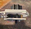
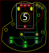
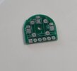
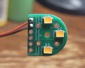
So, Elecrow send me 30 of the circuit boards for the RAD gauge motor and backlights, instead of he 5 I was expecting... Not bad for $5

Anyway, they look good on first inspection. I'll give them away to anyone wanting to make one of these for just the cost of shipping.

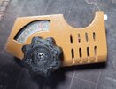
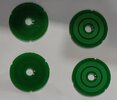
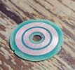
Kind of like the selection knob potentiometers, where I only needed 2, but had to buy 25... I'll send those to anyone who wants one, $1 plus shipping costs...
 

Attachments

  • 458346902_10163589475922656_9214510864435316495_n.jpg
    458346902_10163589475922656_9214510864435316495_n.jpg
    14.9 KB · Views: 65
Ordered the dowels, pins, and threaded spacers for the Radio Dial today, and tweaked the diffuser (the 2 led version) to fit normal 3mm LEDs.
I should be getting the CREE LEDs in a couple days for the Rad Gauge. I got 10 of them so I have some extras to experiment with, or as replacements if I mess it up the first time or 2... I'm going to get my son to solder the LEDs, as he's an expert micro/miniature solderer (that's what he does for a living)
 
Well, batting 500 with Elecrow on the circuit boards. The first one was fine, but the second one was kind of a mess. After several weeks, I emailed them asking what the status was, and it seems like they still didn't understand the concept of slip rings, and leaving one side bare copper. I explained it to them several times weeks ago when they initially asked, they still made the board with the rings covered by solder mask. When I explained again after they sent me pictures of the board, they still didn't seem to understand to leave that side bare... and shipped without fixing it. Guess I'll have to sand them down myself.
 

Attachments

  • Catch28E1.jpg
    Catch28E1.jpg
    122.8 KB · Views: 57
Got the LEDs (Cree JK2835B 6‑V W Class) mounted to 2 of the boards, and did some playing around with resistors to get a good amount of light... 22Ω for the win there... That puts us at 65ma per LED or about 1/3 of their maximum capacity. Digikey had them for 0.04 a piece (I got 10, and shipping was way more than the parts)
 

Attachments

  • 20240911_195217.jpg
    20240911_195217.jpg
    247 KB · Views: 52
Oh, the laser cut gauge glass (2 each for the radio dial and rad gauge) also came in today... I just need to get the Simco MAC motor and the driver board from Adafruit.

On the radio gauge, I'm re-positioning the 2 reduction gears on the side to make them 0.7mm closer to the others. My test fit had them too far apart. I also enlarged the holes on the mounting board, and some of the other pieces. (I need to get these MSLA or SLS printed soon as my FDM printer won't quite make final grade parts) Pictures to follow...
 
Picked up some 1mm diameter stainless steel rod for the radio dial pointer. I also sent the gears (and the parts for the takeup reel) to a SLS printer to get them done right (since I only have an FDM printer). $40 total for all the above.

(note: the 1mm rod was too big, and I didn't want to drill out the dial gear. I wound up cutting a piece of lead off of a 3mm LED and painted it red. That fit in nice enough. The wide flat side looked perfect against the dial gauge that I printed on my inkjet.)
 
Last edited:
I scaled up the prop version of zapwizard's holotape so that it fits nicely into this model... I am thinking of adding the LED, battery, and 555 timer to get a blinky light when the door is opened.
 

Attachments

  • 20240913_140151.jpg
    20240913_140151.jpg
    1.3 MB · Views: 58
  • 20240913_140159.jpg
    20240913_140159.jpg
    680.5 KB · Views: 60
Last edited:
Got the rotor circuit board for the "adapter" today, and sanded off the solder mask that covered the slip rings. Looks good enough
 

Attachments

  • 460581978_10163659344812656_3697936199235295703_n.jpg
    460581978_10163659344812656_3697936199235295703_n.jpg
    58.5 KB · Views: 53
While I'm waiting on the ability to go order the Simco motor, and the motor controller, I'm going to think about an ejection mechanism for the holotapes, since they fit down inside the tape deck so far, and you almost have to turn it upside-down and shake out the tape... I'm not sure if I want just a push to eject on the tape, or something that pushes the tape out as the door rises from the top of the pip-boy... Open to suggestions!
 
Hello! First off, incredible work!! I created an account here just so I could say how cool your design is and that I plan to build one of my own. I've set a goal for myself to complete this in a couple of weeks so I will report back with my progress. :)
Also, to share my plan of action- I am going to attempt to build ytec's 100% model at 85% because I am a small person and I plan to wear it. I plan to scale down your files as well to match. Do you think I may run into any major issues during assembly if I scale down the size?
Thank you for sharing!
Thanks... It's been a journey, and I'm still not done :) I should be getting the MSLA printed parts for the radio gauge today, I still have to buy the SIMCO MAC motor and controller for the rad gauge, and then find some place that can make the dial needle for me. I don't have the tools to do it here (Can't FDM print it, too small)... I'm also still designing a "push to eject" mechanism for the holotape itself. I'm also starting to look into the memory foam pad for the inside. I'm not sure how I'm going to get the right shape or contour...

I think the main issue you'll have is finding a screen that fits. You won't be able to use the 4" square display, you'll have to find one smaller. Also, unless you separate the rad gauge from the display bezel and shrink just the bezel itself without shrinking the rad gauge, you won't fit a simco MAC motor. Using his 100% model one barely fits. I was able to scale down other parts from 115% to 100% without too much hassle (I had to rearrange the electronics in the caddy) but I haven't made a 100% yet with the changes to test them out. For that one, I tried using Adafruit's 3.4" square display in the design, and it fit. You may want to try to find a 3", but with that controller, it has to be an RGB666 pinout. You may also need to use a smaller battery. My one suggestion, is try fitting everthing together in cad first. I'm still using MeshMixer and the mix files I made to check fitment before printing anything. Adafruit and Digikey have 3D models (either STLs or STEP files) for most everything. Anything I can't find a model for, I approximate them with a primitive from MeshMixer itself.
 
Last edited:
Got the MSLA printed parts tested for the radio dial, and had to tweak the screw holes on the top cover, and make the opening in the knob a little larger... After that, everything fits perfectly, and rotates very well. (I've been printing just the top part of the assembly cover, to make the time shorter between tries) The m1.6 posts and screws keep everything together nicely, and I can adjust the tension as well, which is a bonus... I'm printing the final version of the cutout area for the radio knob, and will do a sand/paint routine on it, and final fitting of all the parts. Then put the potentiometer in, and connect the wires to the A-D converter board. I'm going to have different small ranges of the pot trigger the playing each of the 4 different recordings from the radio stations, and maybe have some code to play static if the knob is turning but not near a predefined station.
 

Attachments

  • 20241002_151158.jpg
    20241002_151158.jpg
    1 MB · Views: 75
Had to tweak the cut-out piece that holds the radio dial and gears a bit to get the dial itself to fit in there correctly. I also completely opened the bottom of it up (there was a small piece that went over top the far left screws that I had to remove to get a screwdriver in there easily)... Anyway, it's fitting very well now, and easier to put together... I uploaded the STLs to the google drive.

I attached pictures of the radio dial board, gears, indicator, and backlight. The gears were MSLA printed (think Elegoo Mars 4) and the rest was FDM printed with my printer. The screws are M1.6 x 4mm, The outer gears fit over the M1.6 brass spacer (same as on the other side), and the center piece uses a 2mm x 12mm rod to keep everything in line there. (Again, thanks to zapwizard for the gears. I only modified 2 of them slightly to fit on the M1.6 post)

When testing the light from the 2 LEDs I'm using for back-light, I felt they were too bright as-is (They had a 220ohm resistor already attached to each) so I added another resistor (470ohm) to dim them a bit more. Now to take it all apart, and paint it. I'll have to re-sand the inside of the body after paint, just to make sure it's silky smooth.

Oh, I'm working on a PCB to replace the plastic board, just to make soldering the potentiometer a little easier. Most likely, I'll wind up getting a LOT of extra copies of that one too that I will sell cheap.
 

Attachments

  • 20241012_144610.jpg
    20241012_144610.jpg
    1.2 MB · Views: 83
  • 20241012_234614.jpg
    20241012_234614.jpg
    1.1 MB · Views: 78
  • 20241013_000059.jpg
    20241013_000059.jpg
    540.3 KB · Views: 76
  • 20241012_235521.jpg
    20241012_235521.jpg
    801.7 KB · Views: 78
  • 20241013_000119.jpg
    20241013_000119.jpg
    720.5 KB · Views: 74
  • 20241013_000310.jpg
    20241013_000310.jpg
    1.2 MB · Views: 66
  • 20241013_000317.jpg
    20241013_000317.jpg
    467.8 KB · Views: 63
  • 20241014_090040.jpg
    20241014_090040.jpg
    1 MB · Views: 73
Last edited:
So, while I can definitely solder the 3 wires to the micro potentiometer (Bournes 3382G-1-103G) I like the idea of a PCB to make it all easier. I just have to take the diffuser and remove the LED holder, and then make a longer spacer to go between the diffuser and the LEDs... I have the kicad files, the SVG, and the gerber files on the google drive... $5 for 5 boards through elecrow.
 

Attachments

  • Capture.PNG
    Capture.PNG
    61.5 KB · Views: 48
Last edited:
Yeah, I like the idea of using the SMD LEDs I have from the RAD gauge here too... Better than my 1st prototype with 2 3mm white LEDs hot glued into holders at weird angles (see picture below) Now, I did have these hooked up and lit up with the 5v power supply, but I think I like soldering onto a pcb rather than making a mess of wires.
 

Attachments

  • 20241012_234614.jpg
    20241012_234614.jpg
    1.1 MB · Views: 44
Ordered the PCBs, and a new potentiometer (the other one I had broke). I have enough CREE LEDs to do this board already, so I didn't need more. Should all be here before the weekend.

In the mean-time, I'm going to focus on the push-to-eject system for the tape deck. I don't like that the tape just falls in there, and you have to tilt the whole thing over to get it back out. I'm going to use the 1mm thick rods as the spring for the catch pin, and the same rubber bands to pull the sled. I modeled the track that the pin follows in freeCad, and did the rest in MeshMixer. The lands of the track arch and drop to guide the pin, and the steel rod should keep enough downward pressure on it to keep it where it needs to be (This is kind of modeled after the mechanism used to keep a MicroSD card in place)
 

Attachments

  • Capture.PNG
    Capture.PNG
    117.3 KB · Views: 53
  • Capture3.PNG
    Capture3.PNG
    125.9 KB · Views: 49
  • Capture2.PNG
    Capture2.PNG
    144.8 KB · Views: 51
Ok, ran into a snag with SimCo. They have a minimum order size of 10, and this time the overall cost is too high ($220) for something I only need 1 of. Worse than the potentiometers (I still have 10 of those I'm willing to get rid of) or the PCBs (I have tons extra that I'll give away)...

I'm looking into automotive gauge repair shops, auto recyclers, etc. and then if those don't pan out, I'll look for other micro steppers out there on amazon or ebay... I just won't be able to use the PCB in the way I wanted to.
 
Re-thought the pugh-to-eject again. This time, I'm going back to the USB push to eject and using one of the 2mm rods that I bought for the tape door latch / eject system. I already have a piece cut and bent into shape, and I'm waiting for the 3D parts to print to give it a try. I'm going to get a 5mm wide rubber band and use 2 pieces for the "spring" on the rod. One glued over the piece the rod goes into and swivels around on (left side of the picture below), and one piece held by the 2 sets of washers on the other end. The lower washer is an M3 and the upper one is an M2. They will be held in place with an M2 screw and hold the slider in place as well as the rubber band...
 

Attachments

  • Capture.PNG
    Capture.PNG
    80.7 KB · Views: 46
Back
Top