Rymo
Sr Member
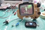
The Zero would be a good choice. It’s a great little board for the price. I used one in my Marksmann GPS replica from The Lost World:Jurassic Park and it worked well for my needs. It’s definitely perfect for projects where limited space is an issue.Just got my hands on one with the same issue. It looks to be also sticking at the initialization screen. Also glad this isn’t a dead thread from years ago, been looking to also get it to some form of use. I really like the idea with the zero and it’s small form factor. I purchased it knowing it was likely to have this issue, and really surprised it even turned on after charging it, with how cheap it was.
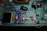
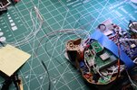
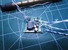
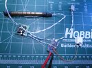
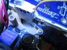
 The next series of videos will show the reduction of size/bulk of the electronics and the close up of the prop, should be fun......