Nerf Aliens Pulse Rifle Build

Re: AW: Nerf Aliens Pulse Rifle Build

Hey 101,

How did you build the SPAS-Cage?

Gesendet von meinem MI 2 mit Tapatalk 2

I used a 40mm plumbing pipe and built sides up with sintra / called foamex in the UK using papercraft plans from:

M41-A Pulse Rifle

There is an internal pipe too which is attached to the pump handle, to make shell chamber open/close.

Hope this helps!
 
Oh and in case anyone is wanting to know the BIG gun Vasquez is using (with the mount) is a modernized MG 42 (or MG 3) from the german army awesome weapons
 
Last edited:
Re: Re: AW: Nerf Aliens Pulse Rifle Build

I used a 40mm plumbing pipe and built sides up with sintra / called foamex in the UK using papercraft plans from:

M41-A Pulse Rifle

There is an internal pipe too which is attached to the pump handle, to make shell chamber open/close.

Hope this helps!

Is that possible with the front gun still functional

Sent from the Garage!
 
Just got my recon today and fitted my raider stock to it. . . I can't wait till the rest gets here!


Sent from the Garage!
 
I've got some sounds for the pulse rifle shooting, shot gun pump action sound, alien cry and hudson talking about pulse rifles, rpg's and sharp sticks (LOL)!

Errr, wasn't that Hicks?

Adding those sound functions seems like a no-brainer. Not the execution, but the idea. Why hasn't this been done before? Especially that licensed sloping barrelled POS from years back. You can put cocking and firing sounds in a dollar store pistol but not a $1k replica?

I may have my doubts about the unlicensed replicas cottage industry, but this is proof positive why DIY is often so much better.:thumbsup
 
Re: Re: Nerf Aliens Pulse Rifle Build

Errr, wasn't that Hicks?

Adding those sound functions seems like a no-brainer. Not the execution, but the idea. Why hasn't this been done before? Especially that licensed sloping barrelled POS from years back. You can put cocking and firing sounds in a dollar store pistol but not a $1k replica?

I may have my doubts about the unlicensed replicas cottage industry, but this is proof positive why DIY is often so much better.:thumbsup

No it was Hudson played by Bill Paxton

And yes I agree

Sent from the Garage!
 
Update for mine. I just shaved down the charging handle and added a counter sunk machine screw inside (M6 * 16) and a type of well nut from work (not sure what kind)
nebyjega.jpg

zetaru2a.jpg

ta7u5u3u.jpg


And a sling mount
uruvataj.jpg


9ysaqe9u.jpg


a8a3y3es.jpg


Sent from the Garage!
 
Last edited:
It was when they were in the apc aftermath initial drop as they where flying to the surface of LV426

Sent from the Garage!
 
Small update.

After wrestling for over a week with various voltage regulator circuits trying to get my little fan integrated into the charge circuit, Majenko came up with the answer and suggested capacitors. I found some on a scrap motherboard I had lying around and pinched a couple, stuck em in my reg circuit, and voila, it worked :D

34F52074-553C-4139-959E-376A39128960-226-00000013C0D441B5.jpg


I noticed they got a little warm after about 15mins, but stayed at a reasonable temp after 45 so I think it's safe to say they won't get too hot.

As it happens though, the only place the little regulator PCB can comfortably go is with the caps next to the fan, so they also share airflow which will help a little to cool them :thumbsup

05BA6701-3D05-4916-A46B-5A3471CBCC5A-226-00000013CBD0571C.jpg


With the fan now working nicely, it was time to concentrate on its needs, so I made intake vents behind the shoulder strap bracket. It's out of the way and won't get accidentally covered if handled while charging:

EEDD9544-951B-4A71-A80E-680F7BC3750F-226-00000013B53406C4.jpg


Hopefully getting the batteries to make the 7cell pack with n/w, then it's to finding places for the mag and mode switches. Once they're sorted, and I've secured the soundboard in the rear of the longshot section (nearest the recon), it's time to make the first few cuts to fit the display, and remove the unwanted bits from the front. That should keepe busy for a little while so I'll hand the thread to you other guys for a change and leave posting till I have something interesting to look at :lol :behave
 
Wow awesome work. So a few questions this chip majenko is working on will it be an all inclusive display with sound or just sound?

Sent from the Garage!
 
It's all there - sound, lights, the works. It has 14.4mm red display, 1.8w speaker amplifier, 6 digital IO / analog input, and an 8 bit general purpose IO port with SPI, I²C, 5xPWM, UART etc in it.
 
Re: Re: Nerf Aliens Pulse Rifle Build

It's all there - sound, lights, the works. It has 14.4mm red display, 1.8w speaker amplifier, 6 digital IO / analog input, and an 8 bit general purpose IO port with SPI, I²C, 5xPWM, UART etc in it.

Ok you lost me after 8 bit IO is that for the sound? And what is the rest sorry I'm a motorcycle mech but microchip stuff I'm at a loss

Sent from the Garage!
 
Re: Re: Nerf Aliens Pulse Rifle Build

Lol thanx for the 4year old perspective. I got what it means I just didn't get this part

"with SPI, I²C, 5xPWM, UART etc in it."

And I was asking what the 8 bit IO Port was for

The rest I got. and I might need some help with wiring diagrams on the IO ports; where I should solder the triggers, speakers and lights and how to programm them in

Sent from the Garage!
 
Well...

SPI and I²C are two methods of chips talking to each other using a serial protocol. PWM is used for controlling the brightness of LEDs, the speed of motors, etc, and a UART is a standard serial port like you get in a PC (but with different voltage levels). Those form part of the 8 bit IO port. Some functions share the same pins, so you can use one or the other, or you can just use them for 8 general purpose inputs and outputs.

The triggers / swiches can solder direct to any of the 6 IO ports you want to use - all the rest of the switching electronics is inside the main control chip, so there is no need for anything other than switches and wires. The speaker connects to the two pins labelled speaker. LEDs you may want to connect up to the PWM pins of the 8 bit IO port if you want them to have varying brighnesses, or just to the normal IO ports like the buttons. They will need resistors with them though - typically 100Ω - or you may damage the chip.

As for programming them - well, that's an entirely different kettle of fish. The module will come pre-programmed with a fairly generic setup on it with some sounds, and a couple of buttons programmed in. You can download the source code (I will have a sourceforge site for it all), and compile it yourself using Microchip's MPLAB-X and XC16 or C30 compilers - tutorials will be online for that. I have tried to abstract most of the work of controlling things to a couple of simple function calls that are easy to use, so you shouldn't have much trouble creating your own firmware.

Think of it like a tiny but powerful Arduino.
 
Ok I lied :behave :lol

I actually managed to get a few bits done in a short time for once.


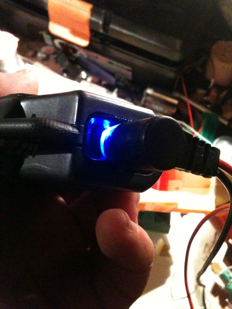
Here's the charging circuit in action (though for some reason two LEDs aren't lighting up, but it's good enough I think).

18C0B6EC-3EB2-40D0-A9F0-33BD47052BC6-169-0000000AE6743F9D.jpg

0C5C8C02-1FCF-4542-9DEB-C460CD4B5488-169-0000000AF1BEDEEB.jpg

(the fan is barly audible once the two halves are screwed together)

Whilst I was still scratching my head and wrestling with making the circuit, Majenko must have taken pity on me (or got fed up with my barrage of stupid questions :p
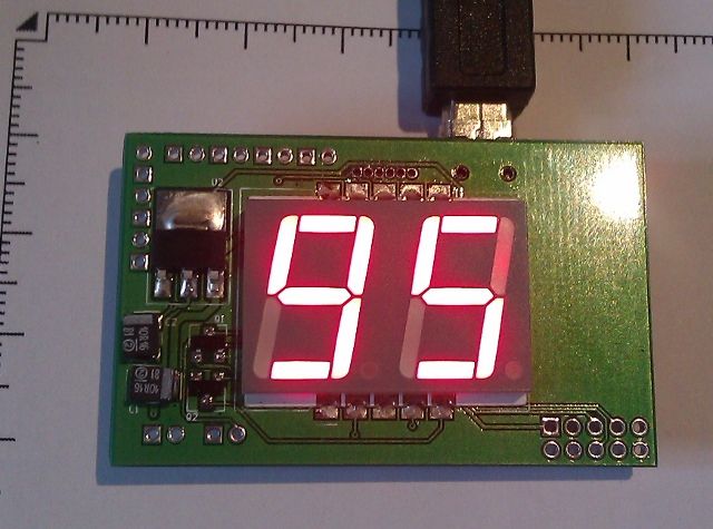
) and very kindly made this tiny custom charge PCB for me which arrived at the w/e (what a dude :cool)

AE6C9391-5ECB-4B81-AFED-AA0EEDBDD510-726-000000B99E3DD900.jpg


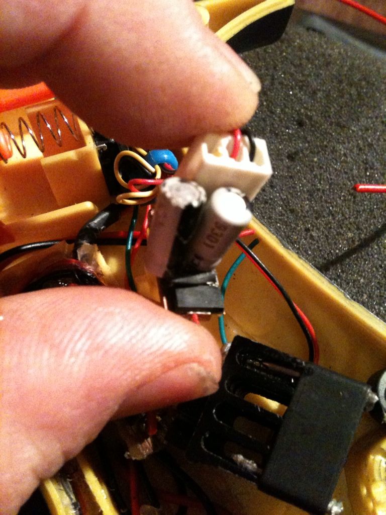
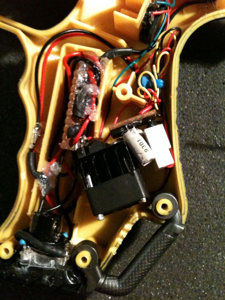
I slapped on a few quick connectors, 3mm LEDs and headers for a fan (I like modular where I can impliment it, it makes for easy troubleshooting) and fed it some juice (cue angelic chorus).
0FE395D0-F849-4003-B361-0353B79B0C2B-726-000000B9B5AF4D4B.jpg


I'm in two minds now, I'm really chuffed I managed to get my charge circuit all working (bar the two LEDs), but it's a bit messy, and majenko's is so cool.

In order not to drive myself mad with indicision I turned to finding a place for the mag and mode switches. In order to keep things simple, I'm attempting to place the electronics on the one side if possible. While the wires are a little close to moving parts, they will eventually be secured out of the way, and it stops the chances of snapping wires when opening the gun up if there aren't any attached to both sides.

I toyed with a reed switch/magnet setup but felt it might interfere with Majenko's FX module being such a strong magnet, so opted for a submicro switch instead.

It was at this point I wish I had a clear recon to use as a template, but after much toying with placement that I discovered the best place was by the magazine latch

3BD80013-3126-42F7-809F-A71B2F1C5968-169-0000000AD80ACEF3.jpg


It needs to be about 1.5 - 2mm from the top of the wall to give the mag overhang and switch button a bit of clearance.

2B8FEC3B-57A1-4DC7-BBFC-500A39E04663-169-0000000ADF64FF4D.jpg


The magazine slides the switch closed very smoothly, and I bent the switch paddle down at the end a bit so it won't catch the mag on its way out. The other thing I noticed is the mag doesn't go in comfortably if put in the wrong way round, this is becouse the guide tracks on the switch side a wider allowing the switch paddle to pass with no probs. the other side is thinner and catches the paddle a bit on the way in making it feel wrong (possibly handy in dark situations :thumbsup).

Just the mode switch to go now and I think it'll end up somewhere near the grenade launcher for ease of access and usability.

To be honest I can't wait to start on the bodywork (especially seeing that awesome SPAS cage mod), and I won't be able to find stash places for the last remaining bits n bobs without the shroud, so after I've made the battery pack it's off to the printers for me on payday.


Oh yeh, and this is Majenko's new MkII PR FX module (for those inquiring earlier)
15C536FD-9A0A-4C2C-8699-C35D3507CAC2-613-000000AA04A0B1B6.jpg

7F7C0C91-3771-4709-B621-CE795B3742F6-613-000000AA012A8D10.jpg


Now I think I can hand this thread back :behave. :lol
 
Back
Top