My P1 Themed Predator Costume with Electronics and Sounds. (Pic Heavy)

Hey Moe how did you secure the backpack onto the actual torso armor? I see you have a piece of bent metal that you screwed onto the backpack and it is folded over to make a hook. But what does it hook onto and is that the only way you have it secured? Thank you
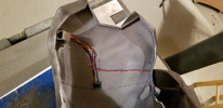
Mine just hooks onto the back of the torso armor. I have a super strong magnet under the armor that the metal latches onto when in position.

Maybe the picture below would better describe the position of the magnet:

1686656405560.png


In this picture, the blue square would represent the neodymium magnet I placed underneath. I used a couple of ones from old Hard Drives.
 
Ciao everyone, I'm having some doubts on head connection to the back via RJ45.

Basically

- MPU6050 has 4 wires
- My three laser diodes are like those ones (1 positive, 1 ground and 1 for signal)

laser.png


How can I user RJ45 (so 8 connections) if four are already reserved for gyroscope?

I know I can join 3 positive in one wire and the same for ground but not sure how to handle the 3 signal cables

Any hints here?

Thank you!

Alessandro
 
Hey Moe did you add any resistors at all to that Arduino? Anywhere along the SDA to SCL?
No. The Arduino Mega regulates the voltage to the SDA SCL just fine.

Ciao everyone, I'm having some doubts on head connection to the back via RJ45.

Basically

- MPU6050 has 4 wires
- My three laser diodes are like those ones (1 positive, 1 ground and 1 for signal)

View attachment 1722586

How can I user RJ45 (so 8 connections) if four are already reserved for gyroscope?

I know I can join 3 positive in one wire and the same for ground but not sure how to handle the 3 signal cables

Any hints here?

Thank you!

Alessandro

You have 3 pins. I would test the ground with the other 2 to see if your laser lights up. if nothing happens, bypass the pins and go directly to the 2 holes beyond them:

1690311359232.png


Just remember to take note of your voltage and use a resistor so that you don't damage the lasers. Mine were rated to 5V and I still used a resistor on all 3 to ensure they didn't burn out.
 
No. The Arduino Mega regulates the voltage to the SDA SCL just fine.


You have 3 pins. I would test the ground with the other 2 to see if your laser lights up. if nothing happens, bypass the pins and go directly to the 2 holes beyond them:

View attachment 1722735

Just remember to take note of your voltage and use a resistor so that you don't damage the lasers. Mine were rated to 5V and I still used a resistor on all 3 to ensure they didn't burn out.

But what I don't understand, in case, is how using 4 connections in the RJ45 (ones available), how this could work if 3 lasers = 9 connections --> possibly 6 can be grouped (3in1 for positive, 3in1 for negative) so 2 in total but we need to add 3 signals so 5 out of 4

:(

Maybe I'm missing something on eletronics :)

Thank you!!

Alessandro

I plan on using these but they only have a positive and a negative I might work for you better? I'm not quite sure why yours has three wires?

HiLetgo 10pcs 5V 650nm 5mW Red Dot Laser Head Red Laser Diode Laser Tube with Leads Head Outer Diameter 6mm Amazon.com
 
But what I don't understand, in case, is how using 4 connections in the RJ45 (ones available), how this could work if 3 lasers = 9 connections --> possibly 6 can be grouped (3in1 for positive, 3in1 for negative) so 2 in total but we need to add 3 signals so 5 out of 4

:(

Maybe I'm missing something on eletronics :)

Thank you!!

Alessandro
Actually, all you need is 1 connectors in the rj45 for the lasers, not 9. 22 gauge wire is more than enough to handle the amperage for 3 lasers. in addition, Since you have 2 devices in the helmet (the lasers and gps chip) you can combine their grounds together. All grounds go to the same place.


1690375233449.png

Look at the above masterful art drawing, All that wiring is contained inside the red circle here:
1690377436182.png


Wire #1 needs a switch to supply power and that's it. Wire 2 can be combined with the gps ground wire. All that wiring stays in the helmet before it hits the RJ45 port.

The laser wires are spliced together before they make contact with the gps chip. Then the laser and gps chip grounds get spliced together(a blue and black wire in this case). Overall, you only need 5 of the 8 rj45 ports for the helmet to run.

Remember, the lasers are turned on by a switch that supplies power to them.

Also note, I'm not 100% certain of the wiring below. The black and red may need to be swapped in order for it to work.

1690375233449.png
 

Attachments

  • 1690376463189.png
    1690376463189.png
    2.5 MB · Views: 38
Actually, all you need is 1 connectors in the rj45 for the lasers, not 9. 22 gauge wire is more than enough to handle the amperage for 3 lasers. in addition, Since you have 2 devices in the helmet (the lasers and gps chip) you can combine their grounds together. All grounds go to the same place.


View attachment 1722954
Look at the above masterful art drawing, All that wiring is contained inside the red circle here:
View attachment 1722956

Wire #1 needs a switch to supply power and that's it. Wire 2 can be combined with the gps ground wire. All that wiring stays in the helmet before it hits the RJ45 port.

The laser wires are spliced together before they make contact with the gps chip. Then the laser and gps chip grounds get spliced together(a blue and black wire in this case). Overall, you only need 5 of the 8 rj45 ports for the helmet to run.

Remember, the lasers are turned on by a switch that supplies power to them.

Also note, I'm not 100% certain of the wiring below. The black and red may need to be swapped in order for it to work.

View attachment 1722954
Moe, thank you for the explaination!

Clear for positive and ground, I will combine...It make more sense and bring efficiency for sure!!

But basically my issue is that those lasers have the 3rd wire which is supposed to be sent for signal to Arduino.

Basically, by clicking on Button (temp. switch) on the gauntlet, I will need to activate trilaser, gyro and servos (shoulder cannon) all together so this is why I still don't understand how can I pilot those without sending signal to Arduino!

:)
The gps chip should be always on with arduino. The other 2 are connected to a toggle switch separate from arduino.

Power comes from battery and branches 2 ways. One branch goes to arduino and gps chip, the other goes to manual latching switches in the gauntlet. These switches are independent of the arduino mega.

The arduino will always be on act as if everything is working but you will not see cannon movement and lasers till you send power to them through the independent switch.

Does that make sense?
 
It’s a different view but I guess yours is absolutely more stable and efficient…

Gyro needs to be on together with the rest and laser+servos powered just through the switch.

It makes absolutely sense..

Let’s go then!

Thank you for your hints!!
 
Actually, all you need is 1 connectors in the rj45 for the lasers, not 9. 22 gauge wire is more than enough to handle the amperage for 3 lasers. in addition, Since you have 2 devices in the helmet (the lasers and gps chip) you can combine their grounds together. All grounds go to the same place.


View attachment 1722954
Look at the above masterful art drawing, All that wiring is contained inside the red circle here:
View attachment 1722956

Wire #1 needs a switch to supply power and that's it. Wire 2 can be combined with the gps ground wire. All that wiring stays in the helmet before it hits the RJ45 port.

The laser wires are spliced together before they make contact with the gps chip. Then the laser and gps chip grounds get spliced together(a blue and black wire in this case). Overall, you only need 5 of the 8 rj45 ports for the helmet to run.

Remember, the lasers are turned on by a switch that supplies power to them.

Also note, I'm not 100% certain of the wiring below. The black and red may need to be swapped in order for it to work.

View attachment 1722954
What size resistor you end up using? Thank you
 
It’s a different view but I guess yours is absolutely more stable and efficient…

Gyro needs to be on together with the rest and laser+servos powered just through the switch.

It makes absolutely sense..

Let’s go then!

Thank you for your hints!!
Hi Moe,

last questions, promised! :)

1) Do you have the scope for each button / switch on your left gauntlet?
There are temporary switches, button, toggle button, etc.
I'm really curious and compare to what I'm building, I'm pretty sure I'm thinking about too many complicated stuffs

2) When you mean resistors, you are considering one for each wire (ground) but what kind of resistors did you use?
A single one in the PCB on the temporary switch or really you put a single resistor for each cable like in the picture above?
In case, what kind of resistors?
As far as I can see from other examples, I thought it was enough to put one on the temp. switch (button) which is connected to all 3 grounds and that's it.

Thank you again!
 
What size resistor you end up using? Thank you
I don't think I used more than an 85 ohm resistor on a 5mW red laser to make sure the 5V got dialed back to around 3.3v assuming a 20mA forward voltage. The red light does dim but it's better than if it burned out and I had to replace it like I did on my halo helmet.

Hi Moe,

last questions, promised! :)

1) Do you have the scope for each button / switch on your left gauntlet?
There are temporary switches, button, toggle button, etc.
I'm really curious and compare to what I'm building, I'm pretty sure I'm thinking about too many complicated stuffs

2) When you mean resistors, you are considering one for each wire (ground) but what kind of resistors did you use?
A single one in the PCB on the temporary switch or really you put a single resistor for each cable like in the picture above?
In case, what kind of resistors?
As far as I can see from other examples, I thought it was enough to put one on the temp. switch (button) which is connected to all 3 grounds and that's it.

Thank you again!
I do not have a scope for the buttons but here in my button layout:

1690475881241.png


And video showing action:

Only 4 resistors were used total in this setup.
3 For the Lasers: Resistors are 1/4 watt 85 ohm resistors used only on the lasers (although thinking about it, I could have gotten away with just one for all 3 at 1/4 watt)

1 For the reset switch (now looking back I'm pretty sure this switch is useless and can be removed totally) But use as large of a resistor as you can in the setup below:

I think I used 2M ohm 1/4 watt resistor.
1690477002430.png
 
Hey Moe, you said you're using a different power supply for the gauntlet? And what is it? Thank you!
I did not run a different power supply in the gauntlet, I ended up splitting off from the power supply in the back pack and used 2 of the Cat 5 wires for (+) and (-) to bring it down to the gauntlet.
 

Your message may be considered spam for the following reasons:

If you wish to reply despite these issues, check the box below before replying.
Be aware that malicious compliance may result in more severe penalties.
Back
Top