You are using an out of date browser. It may not display this or other websites correctly.
You should upgrade or use an alternative browser.
You should upgrade or use an alternative browser.
My P1 Themed Predator Costume with Electronics and Sounds. (Pic Heavy)
- Thread starter MoeSizzlac
- Start date
Mrdchavez
New Member
Moe I'm still having problems with the I2C. My lan cable is about 12 in cat 8. Everything works but the cannon stops working for the servos I should say after about 45 seconds to a minute and then sometimes I'll have to manually reset it or else it'll just stop completely and I have to turn off and on the Arduino. I feel like all my I2c wires are short feel the whole thing is less than 2 m maybe? Maybe a meter and a half? From the Arduino straight to the mpu6050. What do you think is causing the servos to stop? The MPU I had it connected to 5 volts on the Arduino and then I switch it to 3.3 v and it works for a little bit longer but still stops. Thank you for your time!
delorean3154
New Member
What brand/model of hardhat did you all use for this? I'm having a tough time finding one that fits in the brackets correctly without making the parts way up too high on my head.
PS Thanks again for all the work Moe and KSJ put into this, I am learning a ton and have a lot of fun!
PS Thanks again for all the work Moe and KSJ put into this, I am learning a ton and have a lot of fun!
ksj
Well-Known Member
If memory serves the third in the code base used was not used really.I know you used 2 Servos, did you just not put the third? or did you delete any lines in the arduino code?
thx again!
You have X, Y, Z axis (Yaw, Pitch, Skew) on the magnetometer/gyroscope. You just need yaw and pitch or in the camera world pan and tilt to move a camera. There is no need to skew the arm just move it up and down and left and right.
Most all gyroscope/magnetometer based movement/tracking setups with servoes just set them up for pan and tilt. Skew would only be used in cases of cameras that have stabalization needs for ultra accurate imaging on mobile gimbles (camera arms.)
as far as code goes you can either not hook up the third servo or comment out the lines with the # character or a section with the #* *# set.
ksj
Well-Known Member
Moe I'm still having problems with the I2C. My lan cable is about 12 in cat 8. Everything works but the cannon stops working for the servos I should say after about 45 seconds to a minute and then sometimes I'll have to manually reset it or else it'll just stop completely and I have to turn off and on the Arduino. I feel like all my I2c wires are short feel the whole thing is less than 2 m maybe? Maybe a meter and a half? From the Arduino straight to the mpu6050. What do you think is causing the servos to stop? The MPU I had it connected to 5 volts on the Arduino and then I switch it to 3.3 v and it works for a little bit longer but still stops. Thank you for your time!
Check the power draw requirements on your servos. That sounds like you are overloading the power supply abilities of your arduino.
A shield like this will have power separated for the servos and can supply up to 5 amps continuous:

Adafruit 16-Channel 12-bit PWM/Servo Shield - I2C interface
You want to make a cool Arduino robot, maybe a hexapod walker, or maybe just a piece of art with a lot of moving parts. Or maybe you want to drive a lot of LEDs with precise PWM output. Then ...
 www.adafruit.com
This one will allow your arduino to play sounds:

Adafruit "Music Maker" MP3 Shield for Arduino w/3W Stereo Amp
Bend all audio files to your will with the Adafruit Music Maker shield for Arduino! This powerful shield features the VS1053, an encoding/decoding (codec) chip that can decode a wide variety ...
www.adafruit.com
This is the final setup I used on my prior arduino setup using that shield and a music maker board
Code:
/***************************************************
This is an example for our Adafruit 16-channel PWM & Servo driver
Servo test - this will drive 8 servos, one after the other on the
first 8 pins of the PCA9685

Pick one up today in the adafruit shop!
------> http://www.adafruit.com/products/815

These drivers use I2C to communicate, 2 pins are required to
interface.

Adafruit invests time and resources providing this open source code,
please support Adafruit and open-source hardware by purchasing
products from Adafruit!

Written by Limor Fried/Ladyada for Adafruit Industries.
BSD license, all text above must be included in any redistribution
* Nunchuck control for four servos and two button inputs
* Honus 2007
* This allows the use of a Wii nunchuck as an input device and is modified/extended from the original code
* by Tod E. Kurt and Windmeadow Labs
*2007 Tod E. Kurt, http://todbot.com/blog/
* Copyright 2011-2013 Gabriel Bianconi, http://www.gabrielbianconi.com/
*
* Project URL: http://www.gabrielbianconi.com/projects/arduinonunchuk/
*
* Based on the following resources:
* http://www.windmeadow.com/node/42
* http://todbot.com/blog/2008/02/18/wiich ... available/
* http://wiibrew.org/wiki/Wiimote/Extension_Controllers
* Based on the following resources:
* http://www.gammon.com.au/blink
*
*/
// www.facebook.com/ArduinoCenter
// https://blog.underc0de.org/arduino-wii- ... o-motores/
// Original Code base credited to Undercode
// Code adapted from Sean Maio Crybabyfx setup
//https://github.com/outcry27/crybabyFX
// Updated by knoxvilles_joker 2017
// http://facebook.com/knoxvillesjoker
// more instructions documented at
// http://alienslegacy.com

#include "ArduinoNunchuk.h"
#include <Servo.h>
#include <Wire.h>
//#include <XLR8Float.h>
//#include <XLR8Servo.h>
#include <Adafruit_PWMServoDriver.h>
#include <SPI.h>
#include <Adafruit_VS1053.h>
#include <SD.h>

// These are the pins used for the music maker shield
#define SHIELD_RESET -1 // VS1053 reset pin (unused!)
#define SHIELD_CS 7 // VS1053 chip select pin (output)
#define SHIELD_DCS 6 // VS1053 Data/command select pin (output)
#define CARDCS 4 // Card chip select pin
#define DREQ 3 // VS1053 Data request, ideally an Interrupt pin
Adafruit_VS1053_FilePlayer musicPlayer = Adafruit_VS1053_FilePlayer(SHIELD_RESET, SHIELD_CS, SHIELD_DCS, DREQ, CARDCS);
//end servo shield declarations

// called this way, it uses the default address 0x40
Adafruit_PWMServoDriver pwm = Adafruit_PWMServoDriver();
//Creates the objects to control the servos
ArduinoNunchuk nunchuk = ArduinoNunchuk();

#define SERVOMIN 150 // this is the 'minimum' pulse length count (out of 4096)
#define SERVOMAX 570 // this is the 'maximum' pulse length count (out of 4096)
int pulseWidth1 = 0; // Amount to pulse the servo 1
int pulseWidth2 = 0; // Amount to pulse the servo 2
int pulseWidth3 = 0; // Amount to pulse the servo 3
long lastPulse1;
long lastPulse2;
long lastPulse3;
int xjoystick;
int yjoystick;
int xtilt;
//const int SoundPin1 = 14;
//const int SoundPin2 = 150;
const int servoPin1 = 9; // Control pin for servo motor
const int servoPin2 = 5; // Control pin for servo motor
const int servoPin3 = 10; // Control pin for servo motor
const int ledPin1 = 2; // Control pin for LED 1
const byte ledPin2 = 15; // Control pin for LED 2
const int servoPin4 = 4; // Control pin for servo motor
int pulseWidth4 = 0; // Amount to pulse the servo 4
long lastPulse4;
int minPulse = 150; // minimum pulse width
int loop_cnt=0;
int ytilt;
int refreshTime = 4; // the time in millisecs needed in between pulses

void setup() {
Serial.begin(9600);
// Serial.println("PWM Begin");
pwm.begin(); pwm.setPWMFreq(60);
// This moves all servos to minimum positions at start. Good if you do not want overloaded servos
pulseWidth1 = minPulse; pwm.setPWM(servoPin1, 0, 145);
pulseWidth2 = minPulse; pwm.setPWM(servoPin2, 0, 530); // yjoy
pwm.setPWM(14, 0, 530); //second tilt servo
pulseWidth3 = minPulse; pwm.setPWM(servoPin3, 0, pulseWidth3);
pulseWidth4 = minPulse; pwm.setPWM(servoPin4, 0, pulseWidth4);
delay(1000);
nunchuk.init (); delay(1000);
// This initializes the Serial interface functions
// Serial.println("Adafruit VS1053 Library Test");
musicPlayer.begin();
SD.begin(CARDCS);
// printDirectory(SD.open("/"), 0);
musicPlayer.setVolume(20,20);
musicPlayer.useInterrupt(VS1053_FILEPLAYER_TIMER0_INT);
delay(500); musicPlayer.startPlayingFile("/t00next0.wav"); delay(1500); //PLAYS INIT SOUND
}

void loop() {
// This initializes the servo read and write functions
checkNunchuck1(); updateServo1(); checkNunchuck2(); updateServo2();
// checkNunchuck3(); updateServo3();
checkNunchuck4(); updateServo4();
// This checks if buttons are pressed and then turns on two separate LED elements
if (nunchuk.zButton == 1) { musicPlayer.startPlayingFile("/T03NEXT2.WAV"); delay(1900); }
checkzbutton(); checkcbutton();
// This sets and reads the output from the nunchuck and stores them as floating variables
xjoystick = nunchuk.analogX; xjoystick = constrain(xjoystick, 26, 226); xjoystick = map(xjoystick, 26, 226, 0, 180);
yjoystick = nunchuk.analogY; yjoystick = constrain(yjoystick, 26, 226); yjoystick = map(yjoystick, 26, 226, 180, 0);
xtilt = nunchuk.accelX; xtilt = constrain(xtilt, 320, 720); xtilt = map(xtilt, 320, 720, 180, 0);
ytilt = nunchuk.accelY; ytilt = constrain(ytilt, 320, 720); ytilt = map(ytilt, 320, 720, 0, 180);
// This prints the serial status of the nunchuck.
// Serial.print ("Joystick X: "); Serial.print (xjoystick, DEC); Serial.print ("\t");
//Serial.print ("Joystick Y: "); Serial.print (yjoystick, DEC); Serial.print ("\t");
// Serial.print ("X: "); Serial.print (xtilt, DEC); Serial.print ("\t");
//Serial.print ("Y: "); Serial.print (ytilt, DEC); Serial.print ("\t");
nunchuk.update();
// if (nunchuk.cButton == 1) { Serial.print("--C-- "); }
//if (nunchuk.zButton == 1) { Serial.print("--Z-- "); }
//if (nunchuk.cButton == 1 && nunchuk.zButton == 1) { Serial.print("--Z-C--"); }
//Serial.print ("\r\n");
}
// button
// z is the cannon laser. c is the head laser.
void checkzbutton() { if(nunchuk.zButton == 1) { pwm.setPWM(ledPin2, 4096, 0); delay(2000); pwm.setPWM(ledPin1, 4096, 0); delay(300); pwm.setPWM(ledPin1, 0, 4096); pwm.setPWM(ledPin2, 0, 4096); delay(300); delay(300); }}
void checkcbutton() { if(nunchuk.cButton == 1) { pwm.setPWM(ledPin2, 4096, 0); delay(3000);} else {pwm.setPWM(ledPin2, 0, 4096); delay(300); }}
// File listing helper
//void printDirectory(File dir, int numTabs) { while(true) { File entry = dir.openNextFile(); if (! entry) { break; } for (uint8_t i=0; i<numTabs; i++) { Serial.print('\t'); } Serial.print(entry.name()); if (entry.isDirectory()) { Serial.println("/"); printDirectory(entry, numTabs+1); } else { Serial.print("\t\t"); Serial.println(entry.size(), DEC); } entry.close(); } }
// These are the functions to check and set the PWM settings for the servos
void checkNunchuck1() { if( loop_cnt > 10 ) { float tilt = xjoystick; pulseWidth1 = map(xjoystick, 0, 180, 145, 265); loop_cnt = 0; } loop_cnt++; }
void updateServo1() { if (millis() - lastPulse1 >= refreshTime) { pwm.setPWM(servoPin1, 0, pulseWidth1); lastPulse1 = millis(); }
//if (pulseWidth1 <= 170) {pwm.setPWM(14, 0, 130);}
if (pulseWidth1 >= 200) {pwm.setPWM(14, 0, 500);} else {pwm.setPWM(14, 0, 230);}
}
void checkNunchuck2() { if( loop_cnt > 10 ) { float tilt = yjoystick; pulseWidth2 = map(yjoystick, 0, 180, SERVOMIN, SERVOMAX); loop_cnt = 0; } loop_cnt++; }
void updateServo2() { if (millis() - lastPulse2 >= refreshTime) { pwm.setPWM(servoPin2, 0, pulseWidth2); lastPulse2 = millis(); } }

//void checkNunchuck2() { if( loop_cnt > 9 ) { float tilt = yjoystick; pulseWidth2 = map(yjoystick, 0, 180, SERVOMIN, SERVOMAX); loop_cnt = 0; } loop_cnt++; }
//void updateServo2() { if (millis() - lastPulse2 >= refreshTime) { pwm.setPWM(servoPin2, 0, pulseWidth2); lastPulse2 = millis(); } }
//void checkNunchuck3() { if( loop_cnt > 9 ) { float tilt = xtilt; pulseWidth3 = map(xtilt, 0, 180, SERVOMIN, SERVOMAX); loop_cnt = 0; } loop_cnt++; }
//void updateServo3() { if (millis() - lastPulse3 >= refreshTime) { pwm.setPWM(servoPin3, 0, pulseWidth3); lastPulse3 = millis(); } }
void checkNunchuck4() { if( loop_cnt > 10 ) { float tilt = ytilt; pulseWidth4 = map(ytilt, 0, 180, SERVOMIN, SERVOMAX); loop_cnt = 0; } loop_cnt++; }
void updateServo4() { if (millis() - lastPulse4 >= refreshTime) { pwm.setPWM(servoPin4, 0, pulseWidth4); lastPulse4 = millis(); } }Mrdchavez
New Member
Moe, can you sketch it out please? thx man!I don't have a sketch board to draw on easily so I'll try to describe what to do for the Flashlight only:
Step 1) Solder directly to the terminals on the flashlight. Now you have one red wire (Flashlight Positive) and one black wire (ground).
Step 2) Ground the flashlight in the backpack where the battery pack is.
Step 3) FOR FLASHLIGHT ONLY, you need to run 2 wires from the backpack to the gauntlet (5V Power and flashlight positive). There will be other wires for powering the servos, reset button, etc but that is seperate for now.
Step 4) In the gauntlet: From the power in, wire one 5v Power to the double momentary switch (one button only)
Step 5) In the gauntlet: From the power in, wire one 5v Power to the latching switch.
Step 6) From the double momentary, wire the other side of the one button to the Flashlight positive.
Step 7) From the Latching switch, wire the other side of the switch to the Flashlight positive.
Let me know if that is clear. If someone has a easy sketch program to use I will download it and use that to illistrate my point.
Geppetto2023
New Member
I'm almost finished with my build of the P1 Predator. I am very thankful for the sharing of files. I am wondering...
I am using the Adafruit audio FX sound board with 2x2W amp and 16mb memory. I've wired everything up using
4ohm 3W speakers from Adafruit as well, I even tried 8ohm but cannot get the volume level any higher than the
average talking voice. Is there a wat to increase volume above that level? So that I may be heard on a minimum
 crowded environment?
I am using the Adafruit audio FX sound board with 2x2W amp and 16mb memory. I've wired everything up using
4ohm 3W speakers from Adafruit as well, I even tried 8ohm but cannot get the volume level any higher than the
average talking voice. Is there a wat to increase volume above that level? So that I may be heard on a minimum
ksj
Well-Known Member
I'm almost finished with my build of the P1 Predator. I am very thankful for the sharing of files. I am wondering...
I am using the Adafruit audio FX sound board with 2x2W amp and 16mb memory. I've wired everything up using
4ohm 3W speakers from Adafruit as well, I even tried 8ohm but cannot get the volume level any higher than the
average talking voice. Is there a wat to increase volume above that level? So that I may be heard on a minimum
View attachment 1733141 crowded environment?
I use one of these to amplify the sound: https://www.aliexpress.us/item/3256...!sea!US!175759449!&curPageLogUid=KRzcVrJ2td3k
I located the amp and two memphis speakers in the cleaner case.
ksj
Well-Known Member
Moe, if you have access to a copier that can scan to email, just draw out the setup on a piece of paper in color and email it to yourself then upload to the site...Moe, can you sketch it out please? thx man!
Mrdchavez
New Member
Yeah if you don't mind it will be nice to draw this up as additionally on that double momentary switch where are you connecting the wire for sound? If you have three prongs on that double momentary One for flashlight positive and one and one for 5v power and I assume the middle one is for ground. But what about when you press button for sound?I don't have a sketch board to draw on easily so I'll try to describe what to do for the Flashlight only:
Step 1) Solder directly to the terminals on the flashlight. Now you have one red wire (Flashlight Positive) and one black wire (ground).
Step 2) Ground the flashlight in the backpack where the battery pack is.
Step 3) FOR FLASHLIGHT ONLY, you need to run 2 wires from the backpack to the gauntlet (5V Power and flashlight positive). There will be other wires for powering the servos, reset button, etc but that is seperate for now.
Step 4) In the gauntlet: From the power in, wire one 5v Power to the double momentary switch (one button only)
Step 5) In the gauntlet: From the power in, wire one 5v Power to the latching switch.
Step 6) From the double momentary, wire the other side of the one button to the Flashlight positive.
Step 7) From the Latching switch, wire the other side of the switch to the Flashlight positive.
Let me know if that is clear. If someone has a easy sketch program to use I will download it and use that to illistrate my point.
Mrdchavez
New Member
I'm so close to finishing this! But it's still not making any sense this write up along with hooking up the actual sound to three prongs of the double momentary switch. I need help! Haha or at least that's sketch. Thx!I don't have a sketch board to draw on easily so I'll try to describe what to do for the Flashlight only:
Step 1) Solder directly to the terminals on the flashlight. Now you have one red wire (Flashlight Positive) and one black wire (ground).
Step 2) Ground the flashlight in the backpack where the battery pack is.
Step 3) FOR FLASHLIGHT ONLY, you need to run 2 wires from the backpack to the gauntlet (5V Power and flashlight positive). There will be other wires for powering the servos, reset button, etc but that is seperate for now.
Step 4) In the gauntlet: From the power in, wire one 5v Power to the double momentary switch (one button only)
Step 5) In the gauntlet: From the power in, wire one 5v Power to the latching switch.
Step 6) From the double momentary, wire the other side of the one button to the Flashlight positive.
Step 7) From the Latching switch, wire the other side of the switch to the Flashlight positive.
Let me know if that is clear. If someone has a easy sketch program to use I will download it and use that to illistrate my point.
ksj
Well-Known Member
Looks like I need to do a short video on how I wired my gauntlet...I'm so close to finishing this! But it's still not making any sense this write up along with hooking up the actual sound to three prongs of the double momentary switch. I need help! Haha or at least that's sketch. Thx!
MoeSizzlac
Active Member
Sorry for all the late responses so I'll try to address everyone:
Also, only the servos and gps chip receive their power from the arduino board. The rest pull directly from the usb port on the power supply.

The piece of metal was from a flattened 22-Gauge Galvanized Tension Bridging used in construction:

It's ugly, but best I could do till I can get my hands on proper software:

The best advice I could give was use an external personal speaker plugged in with a 3.5mm male to male jack. That's how I got it so loud in my video.
It could be power supply. I'm working with an (always on) power supply. One of the other power supplies I was originally going to use ended up turning off on its own after a little bit of time also. Try plugging in your arduino into a wall supply to make sure it keeps working.Moe I'm still having problems with the I2C. My lan cable is about 12 in cat 8. Everything works but the cannon stops working for the servos I should say after about 45 seconds to a minute and then sometimes I'll have to manually reset it or else it'll just stop completely and I have to turn off and on the Arduino. I feel like all my I2c wires are short feel the whole thing is less than 2 m maybe? Maybe a meter and a half? From the Arduino straight to the mpu6050. What do you think is causing the servos to stop? The MPU I had it connected to 5 volts on the Arduino and then I switch it to 3.3 v and it works for a little bit longer but still stops. Thank you for your time!
Also, only the servos and gps chip receive their power from the arduino board. The rest pull directly from the usb port on the power supply.
I did not. you can see the lines for a 3rd servo in the code after a review. It looks like pin 7 is Horizontal, Pin 6 is Vertical. Pin 5 was unused but was left as side.I know you used 2 Servos, did you just not put the third? or did you delete any lines in the arduino code?
thx again!
I used the inner mechanism from this hard hat. I didn't use the hard hat itself. I created my own strap to go around.What brand/model of hardhat did you all use for this? I'm having a tough time finding one that fits in the brackets correctly without making the parts way up too high on my head.
PS Thanks again for all the work Moe and KSJ put into this, I am learning a ton and have a lot of fun!
The piece of metal was from a flattened 22-Gauge Galvanized Tension Bridging used in construction:
Moe, can you sketch it out please? thx man!
It's ugly, but best I could do till I can get my hands on proper software:
I'm almost finished with my build of the P1 Predator. I am very thankful for the sharing of files. I am wondering...
I am using the Adafruit audio FX sound board with 2x2W amp and 16mb memory. I've wired everything up using
4ohm 3W speakers from Adafruit as well, I even tried 8ohm but cannot get the volume level any higher than the
average talking voice. Is there a wat to increase volume above that level? So that I may be heard on a minimum
crowded environment?
The best advice I could give was use an external personal speaker plugged in with a 3.5mm male to male jack. That's how I got it so loud in my video.
Correct. No resistors.Those switches on the gauntlet specifically the double momentary and rocker switch. there are no resistors connected to it correct?
It should be 4 prongs. Not 3. I'm sorry if the original looked like 3.Yeah if you don't mind it will be nice to draw this up as additionally on that double momentary switch where are you connecting the wire for sound? If you have three prongs on that double momentary One for flashlight positive and one and one for 5v power and I assume the middle one is for ground. But what about when you press button for sound?
Attachments
Geppetto2023
New Member
Thanks! that makes alot more sense. I have had a bowl of noodles going on. Now I'm starting fresh. (Only MPU-6050 and Two Servos are connected to the Arduino. Everything else,(gauntlet power to Adafruit sound FX board(requires positive and ground) Flashlight switch, secondary switch in gauntlet to complete circuit and bring servos, mpu-6050 and lasers to life. Switch on backpack actually enables power to gauntlet. Am I close?It could be power supply. I'm working with an (always on) power supply. One of the other power supplies I was originally going to use ended up turning off on its own after a little bit of time also. Try plugging in your arduino into a wall supply to make sure it keeps working.
Also, only the servos and gps chip receive their power from the arduino board. The rest pull directly from the usb port on the power supply.
Mrdchavez
New Member
Is there any reason why not have most of the stuff come out of 5V from the Arduino versus directly from the battery? Additionally I noticed my MPU 6050 seeing the perform better on 3.3 volts versus 5 volts as in it lasts longer before any failure. Should be that same hitec ones you guys been getting
MoeSizzlac
Active Member
The switch on the backpack actually was the switch from the power pack (black brick). I ended up removing the switch and extending the wires to the back to be able to fully cut power to everything.Thanks! that makes alot more sense. I have had a bowl of noodles going on. Now I'm starting fresh. (Only MPU-6050 and Two Servos are connected to the Arduino. Everything else,(gauntlet power to Adafruit sound FX board(requires positive and ground) Flashlight switch, secondary switch in gauntlet to complete circuit and bring servos, mpu-6050 and lasers to life. Switch on backpack actually enables power to gauntlet. Am I close?
The MPU-650 is always on once the Mega is powered on. There is no switch to turn on the MPU-650 as all the wires are plugged into the Mega.
Servos and Lasers are linked to a single gauntlet switch. Correct.
The Arduino can only output so many amps. I bypass this with most of my wiring to avoid any possible limitations.Is there any reason why not have most of the stuff come out of 5V from the Arduino versus directly from the battery?
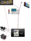
This I don't get as mine work longer than you are getting (I haven't hit a time limit yet). Are you using the same power source as me?Additionally I noticed my MPU 6050 seeing the perform better on 3.3 volts versus 5 volts as in it lasts longer before any failure. Should be that same hitec ones you guys been getting
(Power Source)
No worries!And Moe thank you for taking the time to explain all this I really appreciate it!
ale84iac
New Member
Hi Moe, ksj
I'm really struggling with one unexpected issue...I hope you have some idea
Basically I have Adafruit in the gauntlet and everything always worked fine, I was able to play sounds via buttons in the gauntlet and so on.
At that time power for Adafruit was coming to micro USB port, ground from Arduino GND pin and everything worked without any issues (see video below)
Then I assembled everything via wiring and basically buttons are not working anymore...
This is what I have now in the gauntlet (exactly the same as per video above, no changes) except the battery pack which is providing power instead of micro USB

and of course ground is coming from Arduino via RJ45 (from Arduino to the board, from the board to RJ45 (both Gauntlet and Head)

Notes:
I really appreciate if maybe you can find a few mins sand provide some idea...I don't know anything else I can try.
Alessandro
I'm really struggling with one unexpected issue...I hope you have some idea
Basically I have Adafruit in the gauntlet and everything always worked fine, I was able to play sounds via buttons in the gauntlet and so on.
At that time power for Adafruit was coming to micro USB port, ground from Arduino GND pin and everything worked without any issues (see video below)
Then I assembled everything via wiring and basically buttons are not working anymore...
This is what I have now in the gauntlet (exactly the same as per video above, no changes) except the battery pack which is providing power instead of micro USB
and of course ground is coming from Arduino via RJ45 (from Arduino to the board, from the board to RJ45 (both Gauntlet and Head)
Notes:
- Head is working perfectly, I mean lasers and gyro are working when I power on Arduino
- Gauntlet is receiving power (around 5v) everywhere but buttons are now not working anymore
- Very intersting: if I use multimeter in test mode and i touch pins in adafruit, sounds is working so I really don't understand what's going wrong with all buttons now...
I really appreciate if maybe you can find a few mins sand provide some idea...I don't know anything else I can try.
Alessandro
Similar threads
- Replies
- 4
- Views
- 272
- Replies
- 5
- Views
- 250
- Replies
- 0
- Views
- 1,256
- Replies
- 17
- Views
- 1,914