More details on the Vader ROTJ saber - Please archive

</SPAN><TABLE BORDER=0 ALIGN=CENTER WIDTH=85%><TR><TD CLASS=$row_color>
Killdozer wrote:
<HR></TD></TR><TR><TD CLASS=$row_color>

Maybe I'm imagining it-- I'm willing to be shot down-- does anyone else see what might be holes on the edge of the "tire valve"? Something like... this:


KD
</TD></TR><TR><TD><HR></TD></TR></TABLE><SPAN CLASS=$row_color>


Yes, you are imagining this, there are no holes in the edges, I check my pics again. From all angles I see a solid surface.
 
</SPAN><TABLE BORDER=0 ALIGN=CENTER WIDTH=85%><TR><TD CLASS=$row_color>
fried mon calamari wrote:
<HR></TD></TR><TR><TD CLASS=$row_color>
7.jpg

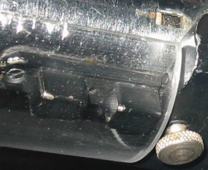
If you look at the spacing of the slot to the grip it seems to difer from the two shots. The shot with the mysterious metal strip looks like a shorter distance to the grips than the other one.
At first I thought it was an illusion given the change in angle, but if you look at the gap vs. the width of the grip, the gap on the left shot is almost as wide as the grip base and the upright and the shot on the right isn't even as wide as one side of the grip ( even if you take into account the distance lost by the leading edge of the grip that's hiding some of the gap)
</TD></TR><TR><TD><HR></TD></TR></TABLE>

I'm not sure I see that. I believe it's an optical illusion caused by a different point of view again, as the angles are significantly different.

<TABLE BORDER=0 ALIGN=CENTER WIDTH=85%><TR><TD CLASS=$row_color>Quote:<HR></TD></TR><TR><TD CLASS=$row_color>
Something else too,
I marked lines on the control box where the angle of offset is. It looks like there are 3 separate positions for the control switch.
</TD></TR><TR><TD><HR></TD></TR></TABLE>

That's probably cos, as I said in my earlier post, the saber has been displayed in at least 3 different venues, and the control box probably was moved (non-intentionally, of course) to a different position each time.

<TABLE BORDER=0 ALIGN=CENTER WIDTH=85%><TR><TD CLASS=$row_color>
Killdozer wrote:
<HR></TD></TR><TR><TD CLASS=$row_color>
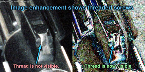
After some heavy staring sessions, here's my take on what may be happening under the midband:

DVrotjctrlbox.jpg


To my eye, the way the shadows fall indicates that the white "strip" is quite thick, possibly only as thick as the light area, but also possibly going right to the core.

What I find really interesting is the area further forward, which looks much deeper than the midband itself-- it looks like they wouldn't even touch! The second diagram illustrates what might be going on...

KD
</TD></TR><TR><TD><HR></TD></TR></TABLE>


KD, what you're saying sounds reeeeaaally interesting, but I'm not sure I understand what you're saying!!
icon_lol.gif


are you saying that the second black strip is a shadow or something?

<TABLE BORDER=0 ALIGN=CENTER WIDTH=85%><TR><TD CLASS=$row_color>
obi1kenny wrote:
<HR></TD></TR><TR><TD CLASS=$row_color>

Yes, you are imagining this, there are no holes in the edges, I check my pics again. From all angles I see a solid surface.
</TD></TR><TR><TD><HR></TD></TR></TABLE><SPAN CLASS=$row_color>

Thank God for that!! For a moment I thought I might have to replace my port plug!!
icon_lol.gif
 
</SPAN><TABLE BORDER=0 ALIGN=CENTER WIDTH=85%><TR><TD CLASS=$row_color>
steveday72 wrote:
<HR></TD></TR><TR><TD CLASS=$row_color>

[Activator Screws]
Kenny - the photo of your modified activator has a sleeve around the frontmost screw, but in the enhanced image I did you can see that screw thread is not covered, but being washed out by the flash photography...

Vader-ROTJ-thread-enhance.jpg


</TD></TR><TR><TD><HR></TD></TR></TABLE>


Right you are, the new one that I modified does have a sleeve around the whole thing as I was trying to go for what I belive is the way it was when it was originally built. I also believe that there is a sleeve still around that screw/spring but part of it has broken off, but not all of it has broken off.


<TABLE BORDER=0 ALIGN=CENTER WIDTH=85%><TR><TD CLASS=$row_color>Quote:<HR></TD></TR><TR><TD CLASS=$row_color>
[Activation Box Mounting]
.....
The following images are quick previews from my 3D modelling program. They show how the two halves line up in relation to the measurements and photos that have all been cross referenced and triple checked against known parts and each other...

Vader-ROTJ-3D-1.jpg

</TD></TR><TR><TD><HR></TD></TR></TABLE>


Those are great models! WOW!
I am glad to finally see someone agree with me that if you were to go with standard Graaflex tubes on this then the overall measurement would show that they are spaced out under the mid-band. As the way I did the first kits and then most people didnÂ’t like that as the wanted to butt the end together. Non-the-less the last inner tube I made can be mounted with the shells flush together or with them spaced apart, as it was just a straight tube and itÂ’s up to the builder to drill holes in the graflex tube and do the mounting. Here is the pic again of the old inner mounting tube:

midband1.JPG


<TABLE BORDER=0 ALIGN=CENTER WIDTH=85%><TR><TD CLASS=$row_color>Quote:<HR></TD></TR><TR><TD CLASS=$row_color>
On my measurements, I found that the rear notch of the activation box is 1mm shorter than the front notch - this now makes sense, after seeing the profiles that show a slope towards the rear (possibly something got chipped off there - it looks like old bakelite plastic anyway, which is very brittle).
</TD></TR><TR><TD><HR></TD></TR></TABLE><SPAN CLASS=$row_color>


You are correct, if we are talking about looking at the box from the profile/side then the back step is smaller that the front, hence the way I made the last boxes. I machined them at a difference of 0.040” with the back being the smaller step. And when I convert your feeble metric system value of 1mm then that comes out to 0.0394” so I would say we are talking about the same thing here. As for the slope, the pics I have show a half ass flat surface but it could have gotten beat up a bit more since those pics were taken even. So optical illusion still maybe.
 
Kenny,

It's good that by not relying on any previously calculated measurements, that we came up with the same results. It shows that the results are verifiable.

LOL "your feeble metric system".

...


Now, about the grips!

I went back to the photos and have found that the area that was thought to be a deep gouge, through the layer of plastic/rubber coating, and into the metal T track underneath ...well, it's not a gouge at all.

I compared it to another photo, which shows that same area and the white/brown patch of color is completely flat.

Then if you look at the areas that do have nicks, cuts and gouges in them (which are deeper than this white area), you'll see that they do not show any metal underneath.

Here's a comparison of the areas...

Grip-Gouge-Comparison.jpg


Steve
 
Right you are Steve.
icon_lol.gif
Metric
icon_lol.gif


Well, here is another interesting pic I enlarged just a bit, nothing too new here, OR IS THERE.

dvROTJunderside.jpg


1.) Is it me or does this hole on the ball catch look like a small slotted screw head in that center hole? It looks this way in maybe one other pic I have too.

2.) Another view of the extra top hole.

3.) This one is for DS, as he wanted his saber to look as crappy as the real thing. Lots of layers of paint, no primer and then just chip away.

Also, at looking at the #3 point, this shows an important thing and that is that the outer band is made from a chrome or reflective type metal tube. It could just as well be a damn sink tube. This pic might not show this point as well, so how about another one.

dvROTJunderside2.jpg
 
Steve, I don't see how the lack of a DEEP gouge proves that it's not metal.

Nobody suggested that the coating or paint was that thick. It's just one layer of rubber coating or plasticote.

And besides, that second picture is taken from such an odd angle, and from a distance that makes it hard to see if there really is a layer missing.

In your same pic that you say shows scratches that don't reveal metal underneath, I see other scratches that DO SHOW silver underneath.


My question is, if it's not a missing piece of the coating, then what is the white/brown spot?

It's defenitely not an added layer to the grips.


I don't have some sort of hidden agenda in trying to prove they're metal. I just think it's pretty damn clear that they are.
 
</SPAN><TABLE BORDER=0 ALIGN=CENTER WIDTH=85%><TR><TD CLASS=$row_color>
Killdozer wrote:
<HR></TD></TR><TR><TD CLASS=$row_color>


DVROTJgap.jpg


DVrotjctrlbox2.jpg


From right to left, I see: bottom tube, shadow, side of white band, top of white band, and an L-shaped shadow on a surface below the height of the bottom tube. These elements could have occurred using Kenny's assembly method, if it had separated somehow:

midband1.JPG


KD
</TD></TR><TR><TD><HR></TD></TR></TABLE><SPAN CLASS=$row_color>

KD,

Your diagram looks great to me but, if the middle bar/white band is the insert tube lip like on Ken's kit, wouldn't that shorten the back tube and elongate the front tube? ( which would put only the front 1/2 inch of the back tube under the clamp band)


Ken,
I'm going to have to say that what looks like the screw slot is the lip from the catch IMHO. The light reflection on the lower right matchs the upper right perfectly. I don't see it in this shot of Brevin's either
Brevin-Vader-ROTJ-5c.jpg


Of course, now the we're starting to realize that there's a good chance that they made little changes to this saber during the various shows, they might have added one to keep it fom moving or whatnot. I'd be curious to see the other shot you mentioned.
 
Well, you are probably right as I only thought it was a slim possiblity that I saw a small screw in the center and thought I would throw it out there for the hell of it. Here is another pic anyhow.

DVrotjlatchhole.jpg
 
It does look like theres a small screw in there...Might be what they used to hold the middle portion of the latch to the saber, especially since the fron is cut off.

BTW concerning the squared holes under the control box, is it me or does the wall of the tubing under the control box look really thick?? Thiscker that the wall of a Graflex???

Mayber its a PVC type tubing in there, this might explain the seam between the grips and the control box...
Im saying mayber the Graflex tube was cut right where the grips end and then the inner ,thicker walled tubing was inserted...
 
I thought the same thing. If you look at the Saber from the "From Star Wars.." book it almost looks like there is a tube-over-tube right where the grips meet the midband, like a graflex tube was butted-up against another tube with an inner tube below.
 
There is SO MUCH great new info and insight in this thread since I last checked in!
I just wish I had more time to respond to all (or even most) of this...but for now, I can only address two things:

First, Steve, INCREDIBLE renderings!!! I'm in complete awe! It's nice to see this saber analyzed with such precision!
icon_smile.gif


Next (and for now, last) point:

</SPAN><TABLE BORDER=0 ALIGN=CENTER WIDTH=85%><TR><TD CLASS=$row_color>
obi1kenny wrote:
<HR></TD></TR><TR><TD CLASS=$row_color>

Well, here is another interesting pic I enlarged just a bit, nothing too new here, OR IS THERE.

dvROTJunderside.jpg


1.) Is it me or does this hole on the ball catch look like a small slotted screw head in that center hole? It looks this way in maybe one other pic I have too.
</TD></TR><TR><TD><HR></TD></TR></TABLE><SPAN CLASS=$row_color>

Oh my gosh.

Kenny, I think you hit the nail on the head...or, shall we say screw?

Yes, I DO BELIEVE that there is a screw there!
Why? 2 reasons:
First of all, in the above photo, I do see what I first thought was a scratch, but now completely believe to be a small slotted screw.
Secondly, as I implied earlier, what would be the purpose of drilling a hole in the middle of the door latch? Since that thing is so abruptly chopped off before the shroud, it would surely "ride up" if only attached with the lower screw (as several people have pointed out, and I've seen from experience!).

MY NEW DOOR LATCH ATTACHMENT THEORY

It has two screws. This is pretty well undeniable, from a "builder's point of view."
icon_wink.gif


NICE CATCH, man!
icon_smile.gif


You guys keep rockin'!
 
Hmm, if the plate is rusted. The prop guys would have wanted to fix the problem by coating it with something protective. Fiberglass resin maybe? To me, the paint looks like an attempt to make the endcap look like metal again.
 
I read through some of the earlier posts and it seems like we assumed it was pvc showing in the recharge ports and the test bulb hole.
Could it be a metal insert similar to what Ken made? But instead of a small raised strip like his in the clamp area, they made the raised portion run from the front of the grips to the edge of the front tube, then necked it down to run through the front and rear tubes (like Ken's)?

They were doing the machining for the Luke saber, so they could have lathed an insert for this.

Either way, I agree with something Killdozer said earlier, They sure spent a lot of energy to make a crappy saber when they could have lathed out a simple MPP replica and thrown a Heiland shroud on it.


Here's something that might have already been discussed on another thread that I missed..

The shroud-
All the shroud parts I've seen look to be square shouldered all the way arond the inside diameter. but looking at these shots, it looks like they are rounded. ( the pic on the left is one of Probe Droids from another thread)
5.jpg

6.jpg

It's kind of hard to see on the front side, i'll try and find a better shot of it.
Was this already brought up somewhere else?
 
</SPAN><TABLE BORDER=0 ALIGN=CENTER WIDTH=85%><TR><TD CLASS=$row_color>
fried mon calamari wrote:
<HR></TD></TR><TR><TD CLASS=$row_color>

The shroud-
All the shroud parts I've seen look to be square shouldered all the way arond the inside diameter. but looking at these shots, it looks like they are rounded. ( the pic on the left is one of Probe Droids from another thread)
5.jpg

6.jpg

It's kind of hard to see on the front side, i'll try and find a better shot of it.
Was this already brought up somewhere else?

</TD></TR><TR><TD><HR></TD></TR></TABLE><SPAN CLASS=$row_color>


Yes, I thought this was comon knowledge. This is the way that I made the shrouds in my last kit. Radiused on both sides.

Anyone have a good pic of my machined shroud, if not I will post one tomorrow, if you want to see a pic.
 
Sorry, not a screw on the ball catch (at least it's not supposed to be).

I have installed several ball catches like this one at work before. The small hole is centered between the two balls so you can see your mark on the door frame when you screw it in to line-up with the spring catch. You don't want to be un-screwing and re-screwing the ball catch several times, the frame won't be strong enough with a bunch of screw holes in it.

The hole is there for alignment during installation. I think I still have one here at home (too big, made of brass) that has the same hole in it. I will try to snap a photo if I find it.
 
No that's cool.
I looked all over the junkyard, but I couldn't find any shots of your newer shroud and couldn't remember that detail on it. The one you have on your website instructions was your older one. ( I almost PM'd ya to ask, too!!
icon_mad.gif
icon_rolleyes.gif
)

( I just found the link to your last kit auction and the pic was there- rounded edges and all!)

I'll leave the post for any other ignorant fools like me
icon_lol.gif
 
</SPAN><TABLE BORDER=0 ALIGN=CENTER WIDTH=85%><TR><TD CLASS=$row_color>
James Kenobi 1138 wrote:
<HR></TD></TR><TR><TD CLASS=$row_color>
Sorry, not a screw on the ball catch (at least it's not supposed to be).

I have installed several ball catches like this one at work before. The small hole is centered between the two balls so you can see your mark on the door frame when you screw it in to line-up with the spring catch. You don't want to be un-screwing and re-screwing the ball catch several times, the frame won't be strong enough with a bunch of screw holes in it.

The hole is there for alignment during installation. I think I still have one here at home (too big, made of brass) that has the same hole in it. I will try to snap a photo if I find it.


</TD></TR><TR><TD><HR></TD></TR></TABLE><SPAN CLASS=$row_color>


James,

I have owned several of the actual door latches, and studied them well!

There is NO HOLE in the center! Instead, there's just a stamp (logo, I guess).

The only methods of attachment are by the top and bottom holes.
Unless some modification was made for this prop, it is unquestionable to think that either 1) the hole in the center is just a random, unexplainable thing that the prop makers had no purpose for putting there, or 2) that the latch would have a solid mounting on the tube without some sort of "extra" help...which I firmly believe is the case.

Glue wouldn't explain anything. As anyone who has seen an actual, authentic English door latch of this type, it would be noted that the bottom is hollowed out a bit, and the sides curve downward. If any type of adhesive was used, it would DEFINITELY show!


2 screws. One large at the end near the midband, one very small in the center of the latch.
icon_wink.gif
 
The ones I have installed looked nothing like the ones from the saber except for being ball-catches. Ther were the same two balls in two boxes mounted on a flat piece of metal. But they were biger, and made of brass.

New out of the box, you had to put a paper template on the cabinet jam, and mark the center, and align the ball catch with the hole that is pre-drilled exactly between the balls on the bottom, just like the one on the saber.

I'm not saying it's not a screw, just saying I have installed ball catches with that hole before, so they are out there.

I'll keep looking for one here if I have one.

The one on this saber looks like it used to have two screw hole tabs and one was cut off, and unless it was glued down also then I would have installed another screw too- I would just be amazed that the builder used such a small screw instead of a big-hunking one like the rest of the saber.
 
I still don't see the screw in the shot. The lower right edge of the hole is what I see as the "slot".
But I understand the concept of needing something else to keep it secure.

What is this under the latch? it doesn't match the lower profile of the latch I have ( thank you Ken!)
Brevin-Vader-ROTJ-5c-latch.jpg


Putty or something?
 
since the base of the latch is flat Im assuming that object under the latch is just the reflection of the underside..
 
Back
Top