Build Log - Endor Bunker Bomb / Proton Grenade (WannaWanga)

zjunlimited

Sr Member
Edit: Finished Prop and Video review

==============
Continuing along with my ROTJ props and builds, next up is the Bunker Bomb kit from WannaWanga. You can find this kit here.

What can I say? Roy is known throughout this hobby to delivery quality parts and kits and this certainly did not disappoint.

Here's a quick first look video of the contents of the kit and my initial thoughts.

Paint / Finish Materials
  • Krylon Grey Primer - body and base
  • Krylon Popsicle Orange - body
  • 3M Super 77 adhesive - body and base
  • Archive-X Earth - body and base
  • Archive-X SP Daylight Red and SP Armour Yellow - panels
  • Vallejo Gloss Black Primer - resin parts
  • Vallejo Metal Color Duraluminum - bell knob
  • Archive-X Engine Black, Earth, Boxcar Red - bell knob weathering
  • Archive-X Engine Black, Weathered Black, Earth, SP Lettering Grey - general weathering
  • Molotow Chrome Paint - dynodes
  • Future Floor Gloss - dynodes
 

Attachments

  • 01 Kit 01.jpg
    01 Kit 01.jpg
    2.4 MB · Views: 27
Last edited:
Initial Prep and Painting

After everything was clean and dry, I gave the base and the body a light coat of Krylon grey primer to bring out any imperfections. With the cast being so clean to start and being white, it was tough for me to see any areas of concern. I was quite satisfied that there was only this area on the base that required a bit of filler.
04 FIller 03.JPG


Instead of using the Tamiya diorama pavement effect to give the body and base texture (didn't have any on hand) I decided to use Super 77 Spray adhesive to create that texture effect. I followed that with another light coat of primer. I knocked down the texture later in the process.
05 Main - 01 Texture Spray.JPG


05 Main - 04 Texture Spray.JPG


In the reference photos, you can see several areas where the underlying orange color of the Kango Motor Housing is peaking through. So with the only spray paint I had that had any resemblance of the orange seen on the Kango, I gave the body a coat.

And what you see below is the result...as close as I can get to what the respective vintage parts could have looked like....orange Kango body and gray Plastruct base.
05 Painted 01 - base.JPG


Here are the paints I used for the above steps.
05 Paint.JPG
 
Resin Small Parts Prep

Switching gears now to the resin small parts...surprisingly (or not) these parts were very clean so they did not require much clean up. A quick once over with some 500grit sandpaper was all that was needed.

The bell knob and slider knobs were pretty straightforward to finish since the lines were not complicated.

The resin diodes were a bit more a challenge to clean up due to the curves, nooks, and general design of the piece. I use an emory board to get into the louvers and the surrounding areas the best I could.

Once that was done, I applied a layer of Vallejo Gloss Black primer through an airbrush.

06 Resin Parts Paint 01.JPG
 
Slider Knob

Only the end of these knobs needed to be painted since the rest of the body will be covered. I left the ends with the gloss black primer only since some photos I saw of the vintage part had black shiny ends...plus I did not have regular black glossy paint and this looked good enough.

So first, the aluminum (?) sheets provided in the kit. They had some nice score marks to aid in the alignment of the body.
10 Lever 01 - AL Skin.JPG


I test fit and pre-bent the metal sheet.
10 Lever 02.JPG


10 Lever 03.JPG


Placed 5 dabs of medium thickness CA glue...one on top, 2 on each corner on each side
10 Lever 04.JPG


Held it all together with clamps and let dry.
10 Lever 05.JPG
 
Bell Knob

Ok, gotta admit this was one part of the build as I was looking forward to since I just got in some Vallejo Metal Color acrylic paints and wanted to dry them out.

So in all honesty, I have no idea what the Bell Knob is suppose to look like new but in the reference photos, I can see some silver peaking through the colors. So on top of the Glossy Black, I sprayed Vallejo's Duraluminum. This looked like a nice color and decided to go with it.

These Metal Color paints are quite awesome. It sprayed nicely with only a little flow improver to minimize tip dry (my choice, it's thin enough to spray direct if preferred) and the fact they are acrylic makes it play nice with my health and airbrush.
12 Slide 01 - Vallejo Duraluminum over Black Gloss.JPG

00 Paint 3.JPG

And then started the aging / weathering process using Archive-X Boxcar Red, Earth and Engine Black and a sponge and dab'd away.
12 Slide 03.JPG


The results...which I'm quite happy with which took all of 5 min.
12 Slide 06.JPG


12 Slide 04.JPG
 
Potentiometer Knob

So that should take care of most of the small parts painting steps until I get to the body and base later. The dynodes will be addressed later too.

Moving on to the mechanical part of the build, first up is drilling a hole in the potentiometer knob which allow the bell knob and gear wheel to be attached. The nice part of the knob is that it has these concentric circles on the face. So it was simply find the center and punch a starter hole. I used the smallest punch I had... 5/64, 2mm.

11 Knob 01.JPG


11 Knob 02.JPG


Then using a pin vice and a variety of bit sizes from 1mm to 2.8mm, voila....the hole is drilled.

A few things to note, the 1mm bit is SUPER tiny and fragile. You could start with a larger bit but I didn't want it to run and go askew.
Go slow with minimal downward pressure to minimize breakage. Once you breakthrough to the other side it becomes easier. But take it slow and make sure everything is straight.
11 Knob 04.JPG


11 Knob 06.JPG


11 Knob 08.JPG
 
Potentiometer Wiring

Next up is wiring up the potentiometer using 5mm red clear LEDs and a small battery pack holding 2 CR2032 batteries. The batteries themselves are 3V each but the battery pack wires them up in series so total output is 6V. I doubled checked this with a multimeter.

Color code for my photos: black is battery (-), red is battery (+), blue is LED (-), green is LED (+)

Only the top set of prongs are needed. The two on the bottom won't be used.
Going from left to right in the photo: left is load (-), middle is load (+), right is battery (+)

So I grouped the LED and battery (-) together [blue and black] and soldered it to the left prong; the LED (+) together and soldered it to the middle, and then the battery (+) to the right prong.

13 Potentiometer 04.JPG


Be sure to also use the appropriate resistor to protect your LEDs. A 1/4 watt, 200 ohm resistor was wired in line on the red wire between the battery and the right prong.

Be sure to use appropriate heat shrink.

Final wire setup below.
13 Potentiometer 06.JPG


13 Potentiometer 07.JPG
 
Potentiometer, LEDS, Red Cap Assembly

The red lens caps just snaps into the appropriate holes in the Top Plate. Note the lock washer in the photo that I'll address later.
13 Potentiometer 13 - lock nut.JPG


The nice part of the 5mm LEDs I used is that they snap into the red lens housing. No clue if all 5mm LEDs are the same shape or if these lens caps are designed to accept them but it works. No adhesive was needed to keep them in place. But you gotta be tidy with the heat shrink otherwise I can see it not fitting.
13 Potentiometer 10.JPG


Here's the entire assembly.
13 Potentiometer 11.JPG


Now regarding the lock washer. I ended up removing the piece on the potentiometer that helps secure it to the top plate (see photo below). This piece is inserted into the rectangular opening in the top plate and helps prevents the potentiometer from rotating when you twist the knob on and off.

Well, based on my wiring setup and wasn't sure how much flexibility I needed to orient the potentiometer to a different position, I decided to remove this piece with the full intention that I would use a lock washer to keep everything secure.

Most of you probably won't need to do this if you aren't wiring this up and even if you do wire it, thinking back now I'm not sure if this was even needed. That said though, when I was dry assembling this, it didn't appear to me the nut alone was sufficient to keep everything tight and it may slip over time and use (I'm sure I'm wrong). So I probably would have used a lock washer anyway....so enough of that.
13 Potentiometer 17 - mod.JPG


Overall, I think this turned out nice and gives sufficient light to know that it is on in normal room light environment.
13 Potentiometer 08.JPG


One final comment as to why I used this particular battery pack. It has an on/off switch but more importantly it has a small form factor where if I need to service it (I.e change the battery) I can access it through one of the dynode ports. Just a simple convenience but if this weren't the case, I would still need to remove 4 screws attaching the base to the body but this seems to be a bit more convenient.
13 Potentiometer 20.JPG
 
Bottom Plate and Magnet

Cleaned up the holes with a reemer and files. I did the same with the top plate. And then gave everything a nice scrub down with some 0000 steel wool to even up the finish and give it a nice satin look.
19 Inner Plate 01.JPG


My intention was to always add magnets to this. But the hobby magnets I had were too weak to be effective through the metal.

So I raided an old HDD and extracted the magnet. I then proceeded to cut the magnet in half. Reason being is one uncut magnet makes this off-balance and two uncut magnets would be too powerful. These HDD magnets are no joke. I've pinched my fingers enough when I wasn't paying attention.

So turning to my trusty Dremel and 4-5 cutting disks later....success.
16 Magnet 01.JPG


Then it was back to some CA glue and clamps and done.
16 Magnet 05.JPG


16 Magnet 06.JPG
 
Finishing Resin Dynodes

With accurate dynodes unavailable, I decided to go with the resin version. I was 50:50 honestly between the mirrored version and resin but figured with some effort (and standing 10 feet away...), maybe people won't notice its resin...lol so let's give it a shot. Worst case, I can always get another resin set or a mirrored set or an accurate set as this is probably the easiest item on the prop to replace.

I really, really, really wished one of my Vallejo Metal Colors would have worked but 1) I didn't have the proper color, and 2) even if I did, the photos I saw with chrome or anything truly reflective acrylic paint just didn't look good. I thought of getting Alclad or Spaz but heard it is quite finicky and wasn't in a mindset to experiment....too much that is.

Which then brings me to Molotow. I've been wanting to try these pens out for some time and never had a reason...until now. The fact that I can use it like a pen was super convenient vs an airbrush. So I grabbed a set from Amazon (cheaper than any brick store around me) which included 4mm, 2mm, and 1mm tips. I ended up using all three sizes on the dynodes to get into various places.
00 Paint 4.jpg

The results are quite amazing. Here are some comparison photos between the gloss black primer and the chrome paint.
14 Photomultiplier Dynode - Resin 04.JPG


14 Photomultiplier Dynode - Resin 05.JPG


14 Photomultiplier Dynode - Resin 06.JPG


Now that said, the paint has particular properties that requires a certain technique to apply for the best finish. I practiced on some plastic spoons first but these are my takeaways:
  • paint does not like multiple overlapping lines going across previously painted areas; it leaves marks and looks like crap
  • if the area is small enough and you can cover in a straight line, like the louvers, then it looks great
  • the paint likes small circles; it seems to minimize the lines and the paint is thick and is self-leveling so the results are very nice when applied in this manner
  • once the paint is dry, you can apply another layer over if needed to fill in missed spots and such
Once the chrome dried it is indeed shiny but very sensitive so some type of clear coat is needed. In addition, I intend to weather the dynodes and any paint and weathering effects I plan to use won't stick to untreated chrome.
The problem with clear on chrome though is that it dulls the finish that isn't chrome anymore. I've heard that Alclad and their line of gloss retains the shine but I didn't go down that path.

So here I decided to use Future (I don't have any other glossy clear). In the examples below, the left was with Future sprayed via an airbrush and the right has no clear. You can see the dullness that the clear has on the chrome.
14 Photomultiplier Dynode - Resin 11 Future spray left none right.JPG


That said, it don't totally bad and in fact it works to my advantage if you will since the metal dynodes does not shine as much as chrome and actually after applying the Future, the sheen of the finish resembles much closer to the metal dynodes than a true reflective mirror finish.

I did a side experiment and it appears (to my eye that applying Future via an airbrush results in a slightly more dull sheen than if I dipped or flooded the dynodes with Future via a pipette). Here's how they both turned out using the pipette technique. At least to me it seems to fall in between the photo above.

14 Photomultiplier Dynode - Resin 17 Future clear.JPG


The final step here (which I forgot to do earlier) was to enlarge the holes on the dynodes to accommodate the screws.
Using a pin vice and 1.8mm, 2.0mm, 2.2mm and finally 2.5mm drill bits, the holes were enlarged to the proper size.
The reason I used so many bits was how close the holes (around the rectangular opening) came to the edge. Take your time and go slow.
14 Photomultiplier Dynode - Resin 18 2.5mm bit.JPG


14 Photomultiplier Dynode - Resin 19.JPG


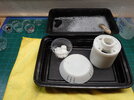
And lastly for those interested, the photo below shows some examples of the Molotow Chrome.
Left Spoon: Molotow applied straight to the spoon using small circles (no primer, no clear)
Right Spoon: Molotow applied in a concentric circle fashion (starting in the middle and expanding outward) that left lines (noticeable towards tip and left side). Left side is tape reside on chrome without clear. After I applied clear to the right side, no tape residue is left behind.
IMG_9979.jpg
 
Base Paint and Rough Assembly

Now that most of the various subassemblies have been completed. I went ahead and started to put everything together.

The boot studs were glued in using CA glue. Be mindful of the orientation of the studs.
20 Assembly 01 - Boot Stubs.JPG


Before I install the remain items, I needed to lay down some Archive X Earth on the body and base.
Since my body was orange, I laid down some Stynylrez black primer in a light coat to knock down the bright orange. But I only applied this to the vertical walls of the body and did not apply it to the top. Reason being is that the reference photos only show the orange peaking through. There's no sign that a black layer was put down (especially noticeable around the inner walls of the red lens and sliders.
This saved me time and paint to cover up the orange.
05 Painted 03.JPG


For the Michell thumb screw, I needed to open up the holes a bit (2.5 or 2.8mm bit) for it to thread in easily. Still I needed to use Vice-Grips for the final turn or 2.
20 Assembly 02 - Michell Thumb Screw.JPG


Potentiometer Assembly was straight forward...just insert the screw from the underside of the knob into the bell knob.
Note, the 20.5mm gap between the top plate and the bottom of the knob for proper vertical height position.
20 Assembly 03 - Bell Knob.JPG


Mulbrod clip must have be the easiest part of this build. Just peal and stick
20 Assembly 04 - Mulbrod Clip.JPG


I had some difficulty with the bottom plate brass screw attachment point. It was suuuuper tight so I used a stepped drill bit to chamfer the leading edge a bit to get the screw to sit and cut the initial threads properly. Without this I simply couldn't get the brass screw to bite. Tapping this would have been preferable but I didn't have anything that matched the threads of the screw.
20 Assembly 06 - Kango Screws.JPG


Annnnd that should cover it. Here a few more shots
20 Assembly 05 - Slider Knob.JPG


20 Assembly 10.JPG


20 Assembly 12 - Red LEDs.JPG
 
Red and Yellow Panel Paint Stencil

Thank goodness Wannawanga provides a nice downloadable stencil from their website since I wasn't particularly thrilled with eyeballing reference photos and tape lines to mask off these sections.

But first, be sure to print the template at 100%. My printer defaulted to 92% and you can imagine, it was too small.

I printed two copies, one for each panel. The idea is that I would cut out each respect color panel and use that to trace the outline of those panels onto the body and base with a pencil.

30 Panel Paint 01 - Red.JPG


30 Panel Paint 06 - Yellow.JPG


30 Panel Paint 09 - Pencil Lines.JPG


I then went ahead and masked off those sections and airbrushed the respective colors. This gave the prop a nice initial base layer of paint. I then went in afterwards with a brush to replicate the brush strokes in the reference photos. Red panel example below.

31 Panel Paint 05 - Red Tape.JPG
 
Aurebesh Letters

Wannawanga was nice enough to provide not just 1 but 2 stencils (just in case you mess up).

So you can use these as a sticker or as a negative stencil.

33 Aurebesh 01.JPG

I chose to use it as a stencil. Be mindful and check reference photos prior to placing the stencil (or sticker if you choose) as it appears to me to be offset to the left based on what I can tell.

33 Aurebesh 02.JPG


A layer of Archive-X Engine Black was used.
33 Aurebesh 03.JPG


33 Aurebesh 04.JPG


33 Aurebesh 05.JPG


And once everything was dry, I applied a piece of glossy packing tape to the letters.
50 Clean 01.JPG
 
Red Highlights behind Dynodes

I almost didn't notice this but when I was scrutinizing the reference photos a bit of red caught my eye behind the top "window" of both dynodes.

So getting a bit creative I located the dynodes with toothpicks, and slid some Tamiya tape between the dynode and the body.
32 Dynode Paint 01.JPG


Then it was simply removing the dynode and brush painted on the red.
32 Dynode Paint 02.JPG


32 Dynode Paint 03.JPG
 
FINISHED!!

Alright, let's wrap this up. Weathering was accomplished referencing a variety of reference photos keeping a balance between how the prop looks today vs screen accurate. That said, the major damage visible on the base skirt of the prop from Celebration occurred post-production. So I chose not to replicate that.

In any case, I used nail files, needle files, 0000 steel wool, a variety of paint brushes and A-X paints (Engine Black, Weathered Black, Earth, and SP Lettering Grey.

Photo dump.....
70 Finished 01.JPG70 Finished 02.JPG70 Finished 03.JPG70 Finished 04.JPG70 Finished 05.JPG70 Finished 06.JPG70 Finished 07.JPG70 Finished 08.JPG70 Finished 10.JPG70 Finished 11.JPG70 Finished 12.JPG70 Finished 13.JPG70 Finished 14.JPG13 Potentiometer 06.JPG

And a wrap-up video including potentiometer wiring, use of templates for the yellow and red panels, and Molotow Chrome on the resin dynodes.
 

Your message may be considered spam for the following reasons:

If you wish to reply despite these issues, check the box below before replying.
Be aware that malicious compliance may result in more severe penalties.
Back
Top