wayouteast
Sr Member
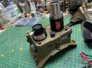
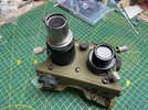
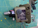
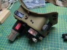
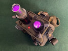
I've had a pair of Spirit Halloween ecto-goggles hanging around for ages. Out of the box, they're a very basic but quite usable 'toy' that gives a pretty good effect from a distance. But they are somewhat lacking in realism up close! Having done a whole bunch of modifications to my Hasbro proton pack, I was inspired to take a crack at the goggles in the hope that I might be able to transform them into something a bit more resembling their real-life counterpart. After two or three weeks of work, this is what I've ended up with. The shape and size are still a bit off, but overall, I hope there's a slight improvement! 

Prep work:
Really the only parts of the original that are left are the body shell and the lenses. The knobs and fixings were replaced with either real ones or resin-printed alternatives from STL files I found on Thingiverse - Hourglass knob (https://www.thingiverse.com/thing:3252213). Battery cover and side focusing knobs (https://www.thingiverse.com/thing:4055803). The moulded knobs, levers, buttons, rivets and fixings were all sanded off and the places where they’d been were filled with car body filler and sanded smooth. Some places like the side knobs (which were going to be re-located to a more accurate placement) needed the holes they left filling with plastic sheet cut to shape before the filling could take place. I also removed the back of the goggles as neatly as I could, retaining both the inner plastic piece and the rubber padding as I would use these later as the basis for the new padding. I stripped out all the original electronics (such as it is - battery terminals, a switch and an LED). I was going to add all new electrics anyway. This included a smaller and less obvious battery (CR2032) so I glued and filled the battery compartment door to make it disappear.
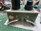
The back of the body (nearest your face) is too square, so I rounded off the corners with a Dremel and sandpaper. I did the same to the inner back pieces to match. I trimmed off the strap slots at the sides and sanded the area where they’d been to match the body edge.
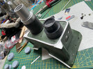
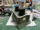
The ‘ridge’ around the front plate was built up out of 3mm plastic sheet, cut into 3mm wide strips and heat-formed to bend 90 degrees at the corners. I built a small jig out of lollipop sticks to do this, and used a hair dryer on the ‘hot’ setting to soften the plastic enough to bend it into shape without it cracking. The ‘wings on either side at the bottom were also built up to profiles with plastic sheet and then filled and sanded to integrate them into the overall body-shape. I also added an extension to the bottom of the goggles so that the snap fasteners to be added there later would fit.
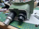
I added a ‘chunk’ to the end of the longer silver lens tube as shown in most photos of the goggles using built up plastic sheet and filler, sanded to shape.
The positions and sizes of the necessary holes for all the new fixings and details were marked and drilled, working from reference photos. There aren’t that many photos of the original props, so I used mostly photos of the Hollywood Collectibles replicas. There are probably still some inaccuracies but I wasn’t that concerned with exact details - the Spirit goggles shape is completely off anyway. All I was after was something that was instantly recognisable as ‘the goggles’ and looked as’ real’ as I could make it.
The resin side knobs were drilled out from the back and had M4 bolts fixed into them using JB Weld so that they could be attached with nuts from the inside later.
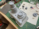
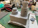
Then more sanding. Lots of sanding. Priming (with grey acrylic car primer) and more sanding…
Painting:
The goggles were given a final coat of grey acrylic primer and let cure for 24 hours.
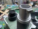
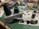
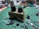
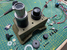
Everything except the lens tubes was masked off, including the clear lenses themselves(!) and the lens tubes were sprayed with a gloss black acrylic. Then everything except the middle part of the largest tube of the long lens was masked and the uncovered area sprayed with matt black acrylic to give the long lens tube a gloss black ring at the bottom and a gloss black ring around the end where the bare metal tubes will be. At the same time, separately, all the knobs and the bolts and screws were also sprayed matt black.
Everything except the bare metal tubes was masked and the metallic lacquer airbrushed on. I used my favourite metallic paint - Alclad II - ‘chrome’ in this case, thinly applied over the gloss black base which I’d polished beforehand. Finally, the lens tubes were masked off and the main body of the goggles was sprayed with Humbrol Olive Drab.
Stickers:
I found a really nice set of stickers on Deviant Art (https://www.deviantart.com/.../Ecto-Goggle-Labels-266762399). The various labels needed quite a bit of re-sizing and adjusting in Photoshop (especially the big ‘instructions’ one which took several attempts) before being printed out on metallic self-adhesive vinyl and cut to size.
Assembly:
The hardware was all attached in position, paying careful attention to the placement of the male and female snap studs, which are 15mm brass heavy-duty studs. Where I could, I attached the press studs in the standard way (as rivets). But there were several areas where the shape of the goggles just didn’t allow this and they were attached with 5-minute epoxy. The side knobs were fixed with nuts from the inside and ‘washers’ made from 2mm silicone sheet.
The battery cover was also attached with a longer M5 cap head bolt and nut, with a silicone ’strap’ (from the same clear/white 2mm silicone sheet) attached during assembly. The faceplate bolts were just screwed directly into their respective holes (self-tapping as they went due to the softness of the plastic). Ditto the smaller screws on the top and the bottom of the goggles, and the optional ‘eye separation adjustment’ knob between the lenses, which is an M5 knurled step thumbscrew (https://www.ebay.co.uk/itm/255861379248?var=555799365292). The ‘hourglass’ knob was left off at this stage since it would be attached later as part of the electrics.
The lens adjustment levers, which are M4 knurled thumbscrews (https://www.ebay.co.uk/itm/265444848695) had their threaded sections cut and filed to length using a hacksaw and were then screwed and glued into position, being careful to keep the ability of the lens tubes to rotate.
All the labels were then attached in their respective positions. The large 'instruction' label on the left side had to be added before the adjustment knob was attached as it extends under the knob slightly.
Electrics:
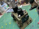
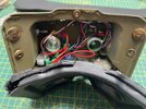
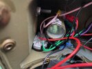
I wanted the lenses to glow in different colours to represent different ‘vision modes’, so I drilled three more 3mm holes in the same area as the existing single green LED on one side, and 4 new 3mm holes at an angle in the side of the inner tube of the other lens. A clear LED lens cover was inserted into the front plate from the front.
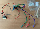
I carefully measured and cut down the shaft of a single pole 12-position rotary switch (https://www.ebay.co.uk/itm/254303918379?var=553808406269) so that when it was inserted from the inside the hourglass knob would fit over it and be flush with the bottom of the goggles. The switch housing had to be VERY carefully ground down on one side to fit inside the goggles. I would only use 5 of the 12 positions (contacts) - OFF/ GREEN/RED/BLUE/PINK (I did try UV but the LED didn’t produce enough visible light to be seen!).
I soldered together a wiring harness with pairs of green, red, blue and pink 3mm LEDs. Their negative leads were all wired directly to the negative terminal of a CR2032 battery holder, and their positive leads to four of the positions on the switch. The positive lead from the battery holder was wired to the common pole of the Switch. I s added another small slide switch to operate a red 5mm LED in the IR Illumination position since I wanted this to be always on while the other colours changed.
Once tested, all the LEDs were hot-glued into position and the switch was fastened in place using its own washer and nut. The battery holder and slide switch were felt free at this stage since they would be hidden between the padding and the back of the goggles eventually. The hourglass knob was attached to the end of the rotary switch’s shaft using a dab of 5-minute epoxy. Using a micro drill, I then drilled through the hourglass and the switch shaft and added a very small hex head set screw to lock them firmly together and add some torsional strength so that the hourglass switch couldn’t slip around the shaft when turned.
Padding and back:
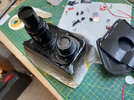
I re-glued the original rubber padding to the back plate of the goggles using superglue, but first I fed the battery holder and slide switch through the eye-hole of the rubber and hot glued them firmly in place at the bottom left corner of the outside of the back plate. They are sandwiched between the rubber and the plastic backplate, and I made sure that the rubber remained unglued at that point so that the battery and the switch are easily accessible.
A strip of black car headliner fabric was then cut and one edge hemmed using a sewing machine. This strip of fabric was superglued to the rubber padding all around the edges with the hemmed edge inwards. The fabric was then folded over the plastic backing plate and superglued tightly in place to form a ring of padding around the whole back plate. A slit was cut in the headliner where the battery holder and slide switch were to allow access. (This looked a bit untidy, so I later added a small covering flap of the same material which is fastened with a strip of velcro).
Finally, the whole backplate, with its new padding, was carefully positioned and hot-glued into the back of the goggles.
Straps:
The straps were constructed from 1” olive drab nylon webbing, I” wide 1.5mm thick black leather for the attachment ends, and thinner olive leather from my scraps box for the ‘back piece’ which I found a template for from Coz_UK on the GBFans forums (https://www.gbfans.com/forum/viewtopic.php?t=4546). The side strips are about 7” long, and the middle strap about 11”.
Press studs were added to short leather strips after those strips were looped over the bar of the slide bar buckles. I measured the leather loops and the press stud positions by eye by holding them over their corresponding studs on the goggles to ensure they’d fit properly. Then the straps were sewn to the back piece, the other ends were heat sealed to avoid fraying and then strengthened with more stitching, and passed through the slide buckles to allow their length to be adjusted.
In retrospect, it would have been better if I’d used something more stretchy for the back piece so that the straps don’t have to be adjusted between ‘over the eyes’ and ‘on the head’.
Final weathering:
The goggles were weathered with black and brown acrylic washes, brushed and sponged on, as well as a very small amount of rust effect wash (Vallejo I think) around the screws and on the metal parts of the lens tube.
The resin knobs were given some ‘bare metal’ wear and tear with dry-brushed silver acrylic paint, and the real metal hardware was given a matching appearance by light scrubbing back through the black paint using a scouring pad and fine sandpaper.
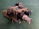
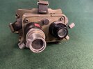
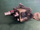
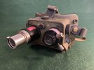
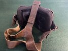
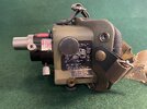
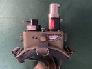
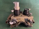
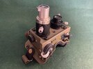
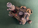
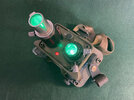
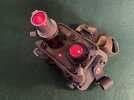
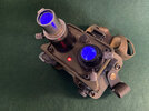
That’s it! Thanks for reading! Beauty shots below! I'm very happy with the goggles which I think look a lot more legit now than the rather simplified original 'toy'. The final colour, by the way, is a bit greener than it appears in these photos - I think the green background shifted the colour balance slightly. They're definitely more olive drab than khaki.
Prep work:
Really the only parts of the original that are left are the body shell and the lenses. The knobs and fixings were replaced with either real ones or resin-printed alternatives from STL files I found on Thingiverse - Hourglass knob (https://www.thingiverse.com/thing:3252213). Battery cover and side focusing knobs (https://www.thingiverse.com/thing:4055803). The moulded knobs, levers, buttons, rivets and fixings were all sanded off and the places where they’d been were filled with car body filler and sanded smooth. Some places like the side knobs (which were going to be re-located to a more accurate placement) needed the holes they left filling with plastic sheet cut to shape before the filling could take place. I also removed the back of the goggles as neatly as I could, retaining both the inner plastic piece and the rubber padding as I would use these later as the basis for the new padding. I stripped out all the original electronics (such as it is - battery terminals, a switch and an LED). I was going to add all new electrics anyway. This included a smaller and less obvious battery (CR2032) so I glued and filled the battery compartment door to make it disappear.
The back of the body (nearest your face) is too square, so I rounded off the corners with a Dremel and sandpaper. I did the same to the inner back pieces to match. I trimmed off the strap slots at the sides and sanded the area where they’d been to match the body edge.
The ‘ridge’ around the front plate was built up out of 3mm plastic sheet, cut into 3mm wide strips and heat-formed to bend 90 degrees at the corners. I built a small jig out of lollipop sticks to do this, and used a hair dryer on the ‘hot’ setting to soften the plastic enough to bend it into shape without it cracking. The ‘wings on either side at the bottom were also built up to profiles with plastic sheet and then filled and sanded to integrate them into the overall body-shape. I also added an extension to the bottom of the goggles so that the snap fasteners to be added there later would fit.
I added a ‘chunk’ to the end of the longer silver lens tube as shown in most photos of the goggles using built up plastic sheet and filler, sanded to shape.
The positions and sizes of the necessary holes for all the new fixings and details were marked and drilled, working from reference photos. There aren’t that many photos of the original props, so I used mostly photos of the Hollywood Collectibles replicas. There are probably still some inaccuracies but I wasn’t that concerned with exact details - the Spirit goggles shape is completely off anyway. All I was after was something that was instantly recognisable as ‘the goggles’ and looked as’ real’ as I could make it.
The resin side knobs were drilled out from the back and had M4 bolts fixed into them using JB Weld so that they could be attached with nuts from the inside later.
Then more sanding. Lots of sanding. Priming (with grey acrylic car primer) and more sanding…


Painting:
The goggles were given a final coat of grey acrylic primer and let cure for 24 hours.
Everything except the lens tubes was masked off, including the clear lenses themselves(!) and the lens tubes were sprayed with a gloss black acrylic. Then everything except the middle part of the largest tube of the long lens was masked and the uncovered area sprayed with matt black acrylic to give the long lens tube a gloss black ring at the bottom and a gloss black ring around the end where the bare metal tubes will be. At the same time, separately, all the knobs and the bolts and screws were also sprayed matt black.
Everything except the bare metal tubes was masked and the metallic lacquer airbrushed on. I used my favourite metallic paint - Alclad II - ‘chrome’ in this case, thinly applied over the gloss black base which I’d polished beforehand. Finally, the lens tubes were masked off and the main body of the goggles was sprayed with Humbrol Olive Drab.


Stickers:
I found a really nice set of stickers on Deviant Art (https://www.deviantart.com/.../Ecto-Goggle-Labels-266762399). The various labels needed quite a bit of re-sizing and adjusting in Photoshop (especially the big ‘instructions’ one which took several attempts) before being printed out on metallic self-adhesive vinyl and cut to size.
Assembly:
The hardware was all attached in position, paying careful attention to the placement of the male and female snap studs, which are 15mm brass heavy-duty studs. Where I could, I attached the press studs in the standard way (as rivets). But there were several areas where the shape of the goggles just didn’t allow this and they were attached with 5-minute epoxy. The side knobs were fixed with nuts from the inside and ‘washers’ made from 2mm silicone sheet.
The battery cover was also attached with a longer M5 cap head bolt and nut, with a silicone ’strap’ (from the same clear/white 2mm silicone sheet) attached during assembly. The faceplate bolts were just screwed directly into their respective holes (self-tapping as they went due to the softness of the plastic). Ditto the smaller screws on the top and the bottom of the goggles, and the optional ‘eye separation adjustment’ knob between the lenses, which is an M5 knurled step thumbscrew (https://www.ebay.co.uk/itm/255861379248?var=555799365292). The ‘hourglass’ knob was left off at this stage since it would be attached later as part of the electrics.
The lens adjustment levers, which are M4 knurled thumbscrews (https://www.ebay.co.uk/itm/265444848695) had their threaded sections cut and filed to length using a hacksaw and were then screwed and glued into position, being careful to keep the ability of the lens tubes to rotate.
All the labels were then attached in their respective positions. The large 'instruction' label on the left side had to be added before the adjustment knob was attached as it extends under the knob slightly.


Electrics:
I wanted the lenses to glow in different colours to represent different ‘vision modes’, so I drilled three more 3mm holes in the same area as the existing single green LED on one side, and 4 new 3mm holes at an angle in the side of the inner tube of the other lens. A clear LED lens cover was inserted into the front plate from the front.
I carefully measured and cut down the shaft of a single pole 12-position rotary switch (https://www.ebay.co.uk/itm/254303918379?var=553808406269) so that when it was inserted from the inside the hourglass knob would fit over it and be flush with the bottom of the goggles. The switch housing had to be VERY carefully ground down on one side to fit inside the goggles. I would only use 5 of the 12 positions (contacts) - OFF/ GREEN/RED/BLUE/PINK (I did try UV but the LED didn’t produce enough visible light to be seen!).
I soldered together a wiring harness with pairs of green, red, blue and pink 3mm LEDs. Their negative leads were all wired directly to the negative terminal of a CR2032 battery holder, and their positive leads to four of the positions on the switch. The positive lead from the battery holder was wired to the common pole of the Switch. I s added another small slide switch to operate a red 5mm LED in the IR Illumination position since I wanted this to be always on while the other colours changed.
Once tested, all the LEDs were hot-glued into position and the switch was fastened in place using its own washer and nut. The battery holder and slide switch were felt free at this stage since they would be hidden between the padding and the back of the goggles eventually. The hourglass knob was attached to the end of the rotary switch’s shaft using a dab of 5-minute epoxy. Using a micro drill, I then drilled through the hourglass and the switch shaft and added a very small hex head set screw to lock them firmly together and add some torsional strength so that the hourglass switch couldn’t slip around the shaft when turned.


Padding and back:
I re-glued the original rubber padding to the back plate of the goggles using superglue, but first I fed the battery holder and slide switch through the eye-hole of the rubber and hot glued them firmly in place at the bottom left corner of the outside of the back plate. They are sandwiched between the rubber and the plastic backplate, and I made sure that the rubber remained unglued at that point so that the battery and the switch are easily accessible.
A strip of black car headliner fabric was then cut and one edge hemmed using a sewing machine. This strip of fabric was superglued to the rubber padding all around the edges with the hemmed edge inwards. The fabric was then folded over the plastic backing plate and superglued tightly in place to form a ring of padding around the whole back plate. A slit was cut in the headliner where the battery holder and slide switch were to allow access. (This looked a bit untidy, so I later added a small covering flap of the same material which is fastened with a strip of velcro).
Finally, the whole backplate, with its new padding, was carefully positioned and hot-glued into the back of the goggles.
Straps:
The straps were constructed from 1” olive drab nylon webbing, I” wide 1.5mm thick black leather for the attachment ends, and thinner olive leather from my scraps box for the ‘back piece’ which I found a template for from Coz_UK on the GBFans forums (https://www.gbfans.com/forum/viewtopic.php?t=4546). The side strips are about 7” long, and the middle strap about 11”.
Press studs were added to short leather strips after those strips were looped over the bar of the slide bar buckles. I measured the leather loops and the press stud positions by eye by holding them over their corresponding studs on the goggles to ensure they’d fit properly. Then the straps were sewn to the back piece, the other ends were heat sealed to avoid fraying and then strengthened with more stitching, and passed through the slide buckles to allow their length to be adjusted.
In retrospect, it would have been better if I’d used something more stretchy for the back piece so that the straps don’t have to be adjusted between ‘over the eyes’ and ‘on the head’.
Final weathering:
The goggles were weathered with black and brown acrylic washes, brushed and sponged on, as well as a very small amount of rust effect wash (Vallejo I think) around the screws and on the metal parts of the lens tube.
The resin knobs were given some ‘bare metal’ wear and tear with dry-brushed silver acrylic paint, and the real metal hardware was given a matching appearance by light scrubbing back through the black paint using a scouring pad and fine sandpaper.
That’s it! Thanks for reading! Beauty shots below! I'm very happy with the goggles which I think look a lot more legit now than the rather simplified original 'toy'. The final colour, by the way, is a bit greener than it appears in these photos - I think the green background shifted the colour balance slightly. They're definitely more olive drab than khaki.


