Build Log: ED-209 Stop Motion Armature

Thanks for the great comments guys! I really appreciate it.

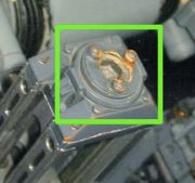
Leg rail progress was made but I'll wait to post images when they're complete. In the meantime, I've been trying to figure out the threaded rod mechanism that traverses the center of the leg rail assembly. This threaded rod rotates along with the plate on the leg rail cap:


I want mine to rotate in like manner, of course! :$

It's clear from this image of the hero puppet that the 'rod' is an allen head screw. I'm estimating it to be a #10-24 screw. After much searching, though, I can't find a fully threaded, 4" #10-24 allen head screw. Boo. Best I could find was a 4" long 1/4-20 screw. 1/4" diameter seemed too big when compared with the hero puppet. I also struggled to discern what the screw passes through which allows 360 deg. rotation. It doesn't look like a bearing but I could be wrong:


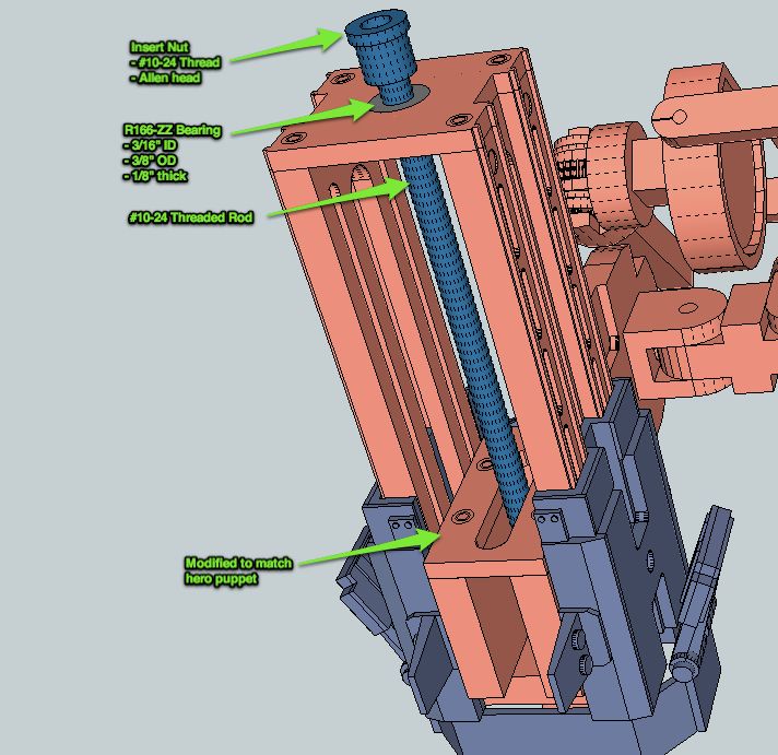
After much thinking and sketching, I've devised a solution:


If anyone has insight or thoughts, feel free to share.
 
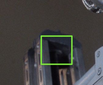
Looks good Chris. There MUST be a bearing in the top of the leg. You can see what looks like the counterpart bearing in the base of the leg. (This is a crop of R04 - Endgame (Legs)106.jpg in our shared material.)

R04 - Endgame (Legs)106.jpg
 
Looks good Chris. There MUST be a bearing in the top of the leg. You can see what looks like the counterpart bearing in the base of the leg. (This is a crop of R04 - Endgame (Legs)106.jpg in our shared material.)

A bearing is my best estimation as well. I believe my design will replicate the mechanical motion just fine. I think deviations from the hero puppet will be minor cosmetics. I'm 98% certain I'll use the design laid out. My next step is to recreate the leg rail cap in SketchUp. This will clarify the final length of the threaded rod.

Once this is resolved, I'll move onto the 'guts' of the box the threaded rod passes through. I know the rod passes through something in that box but I have no clue what it might be. I am almost certain, though, that the slide motion (up and down the leg rails) is decoupled from the threaded rod. In other words, I don't think Tippett turned the rods to move ED up and down the leg rails. There are instances in the movie where the rods turned but the body did not move up or down. I could be wrong, though. If anyone has thoughts please share.

Another piece of this puzzle to figure out! :wacko
vectorzero: Thanks for your input! :thumbsup
 
Last edited by a moderator:
Yep, not clear on the rod thing myself...something else to discover and trying to come up with another idea:confused
 
This is a really interesting build & love the attention to detail & the whole process :thumbsup

I'd always assumed the threaded rod made the box go up & down just like a two poster ramp. Interestingly on a two poster ramp the threaded rod goes through a large bronze nut which moves up & down it. It also crossed my mind that you could use an "Oilite" flanged bush top & bottom of the threaded rod if space is an issue.


Just a thought :)

Edit: http://www.getyourbearings.co.uk/flanged-oilite/aj030504.html

There's some good shots of the leg mechanisms here, I'm sure you've seen this already though :)
http://www.youtube.com/watch?v=z8o6ACD7v1E
 
Last edited:
I've been staring at this shot for a while. The bearing in the base of the leg rail has a definite flange, and looks to locate the block through which the threaded rod passes when it is in the 'down' position. This means the slot is wider than the rod, and to me further supports the idea that the slot in the block which rises up and down the leg is not connected to the rod at all.

Ed_59.jpg

The articulation of this whole knee section is independent of the mechanics when you study frame by frame. The piston group appears to connect to a round plate on top of the leg rail. In reality the pistons are totally independent as this shot shows. I think ED's ride height is set by tightening the black pins on (arrowed) on each side of each leg. Maybe I'm hallucinating but is there a hex in that pin?

IMG_0845.jpg

My 2 cents!
 
Coming along nicely! Your ED is gonna be sick!

btw, added some new renders of my virtual ED. Lemme know if you need any parts!

Robbins Digital Art

Awesome 3d model! Thanks for the help, too. :cool

This is a really interesting build & love the attention to detail & the whole process :thumbsup

I'd always assumed the threaded rod made the box go up & down just like a two poster ramp. Interestingly on a two poster ramp the threaded rod goes through a large bronze nut which moves up & down it. It also crossed my mind that you could use an "Oilite" flanged bush top & bottom of the threaded rod if space is an issue.


Just a thought :)

Edit: http://www.getyourbearings.co.uk/fla.../aj030504.html

There's some good shots of the leg mechanisms here, I'm sure you've seen this already though :)
Robocop - 08 The Boardroom: Storyboard with commentary by Animator Phil Tippett - YouTube

Thanks! These are great thoughts. I've pondered the oiled bushing idea as well.

I've been staring at this shot for a while. The bearing in the base of the leg rail has a definite flange, and looks to locate the block through which the threaded rod passes when it is in the 'down' position. This means the slot is wider than the rod, and to me further supports the idea that the slot in the block which rises up and down the leg is not connected to the rod at all.

The articulation of this whole knee section is independent of the mechanics when you study frame by frame. The piston group appears to connect to a round plate on top of the leg rail. In reality the pistons are totally independent as this shot shows. I think ED's ride height is set by tightening the black pins on (arrowed) on each side of each leg. Maybe I'm hallucinating but is there a hex in that pin?

Neil, I've stared at those images for what seems like days. After reviewing the stills, I may be altering my opinion about the link between the slider box and the threaded rod. They may be coupled, in fact. I'm sketching up (no pun intended) my thoughts and will post something this evening. I'll present in an exploded view so we all can see the idea and mechanics clearly.

- - - Updated - - -

Looks like a hex screw to me for sure, and the flanged bearing, looks like its nylon???

Lee - there's definitely a nylon-ish material that sits on both sides of the threaded rod.
 
Hmm

Perhaps a threaded collar with two projections that lock into the 'counterweight' along the axis of those black pins?

Sure would simplify the animation if you could twirl the main threaded rod, and raise and lower the knee that way. You wouldn't need to keep locking and unlocking the knee joint that way.

Neil
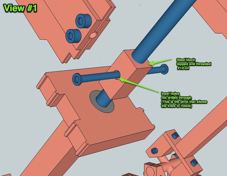
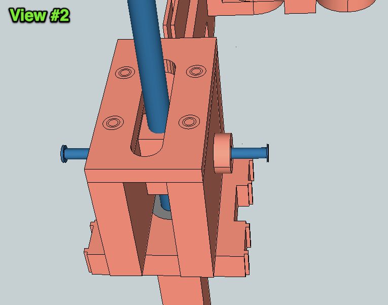
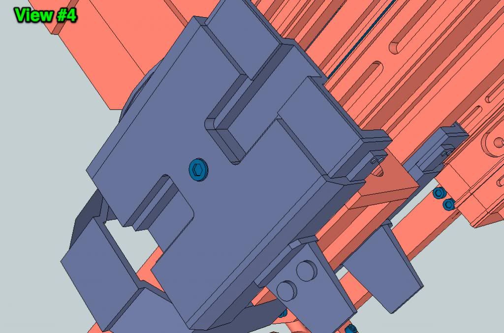
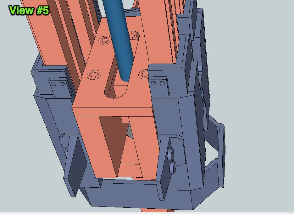
Yes, agreed on the animation. The whole upper body must maintain position when moved up/down the rails. Mechanically, based on other inspections of the joint, it makes most sense to use the strength of the threads to maintain the position. Otherwise, a clamping mechanism is needed. I don't see evidence of clamping mechanism aside from the two black screws at the box's pivot point. I'm nearly convinced that they are NOT being used for any substantial mechanical holding aside from attaching the rail shell to the aluminum rail.

Pictures are worth lots of words. I'll illustrate my thinking this evening.
 
Hi All,

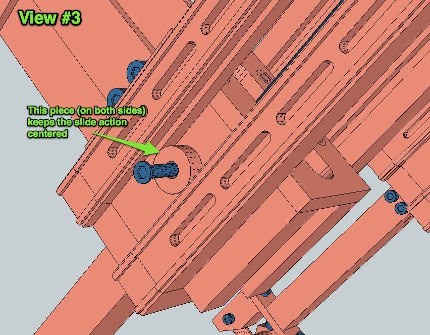
Here are the images that will hopefully illustrate my thinking on Ed's rise/lower motion. This design constantly engages the threaded rod allowing the rise/lower motion and maintains the position at all times. No mechanical clamps needed. Rise/lower is controlled by turning the threaded rod. I must admit, even if this is not how the original puppet functioned, I like it regardless. It just seems cool to have this linear motion!

Thoughts and suggestions welcomed:


I would agree thats the way it was done. I made a similar design for the breathing mechanism for the Taun. Simply rotate the screw and the threaded block moves up and down.
Screen Shot 2014-03-01 at 1.43.34 pm.png
 
I would agree thats the way it was done. I made a similar design for the breathing mechanism for the Taun. Simply rotate the screw and the threaded block moves up and down.

Awesome. With that, it's settled then. The threaded rod in my ED will actuate the rise and lower motion. I received the last of the mechanical parts from McMaster Carr on Friday. Build progress to commence this week.

Thanks everyone.
 
Ah o.k. now I see (thanks ds5500)and keep up the good work CheesyGrin these rendering are beautiful:cool
 
Yep, Shawn has posted his build already and it's going to be a huuuge one. More ED-209 on the RPF: I can live with that;)
 
This thread is more than 9 years old.

Your message may be considered spam for the following reasons:

  1. This thread hasn't been active in some time. A new post in this thread might not contribute constructively to this discussion after so long.
If you wish to reply despite these issues, check the box below before replying.
Be aware that malicious compliance may result in more severe penalties.
Back
Top