CheesyGrin
Active Member
Hi All,
A long time has passed with no updates. I had to take a break and handle life stuff. I see that there's been some discussion, though. That's great! I picked the ED back up this week. I'll reply to some of the comments and provide a build update.
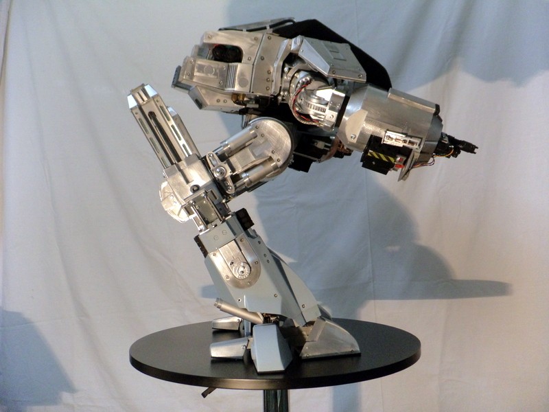
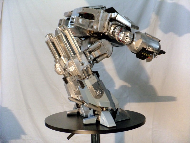
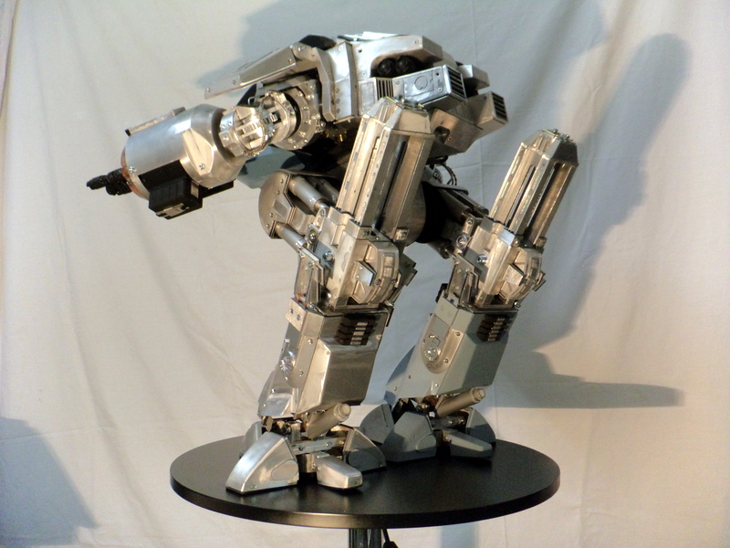
Thanks for the link and the kind words! The Chronicle ED is fantastic. I suppose you can't get any more accurate than direct casts from the movie prop. The pics were extraordinarily helpful and very timely.
I checked out your blog - your build is fantastic! Very impressive metal working skills. I wish I could read French. :cry
OK, here's where I am: Since my last update, I've been realizing the potential of the 3D printer. I can print nearly anything. It's really a huge asset in my tool set. With that, it's only as good as my 3D design. Up to this point, I've relied on Sketchup to design the ED209 armature. Sketchup has been great for what it is and it does it's job very well. But it does not export very cleanly to .stl format, which is the standard 3D printer file format. My model is also not a true solid model in Sketchup. This is the primary reason Sketchup does not export .stl files well. So, I've spent my downtime learning a new design tool - Autodesk Fusion 360. Fusion is a true parametric-based, solids modeling application. It exports to .stl VERY well. It's also free for the hobbyist. I'm sold. The process of re-design in Fusion forced me to evaluate some of my original assumptions about the dimensions and construction of the armature. I believe this model to be more accurate to the original. Again, the Chronicle pics were invaluable.
Here's my new model:
Another thing I did in my downtime was think about my approach to this build. Machining the parts has been a blast. It's my goal to use this build as a learning project, teaching myself to machine. So far it's been a successful journey towards that goal. One of the things I've learned,though, is that machining is a slow, laborious process where one mistake can scrap hours of hard work. This can be frustrating to say the least. I think I've found a better way.
With my 3D printer and new design, I have the ability to rapidly prototype parts and make assemblies much faster than machining them. As I'm working out the mechanics of an assembly, I can design in Fusion and send the design straight to my 3D printer. I can hold a working model in my hand in a fraction of the time it takes to machine the same model.
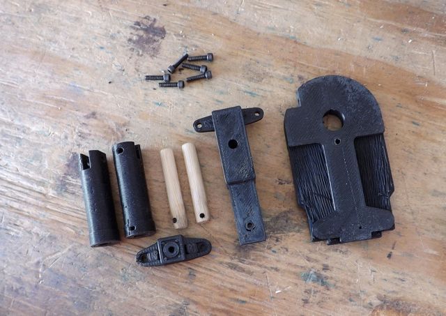
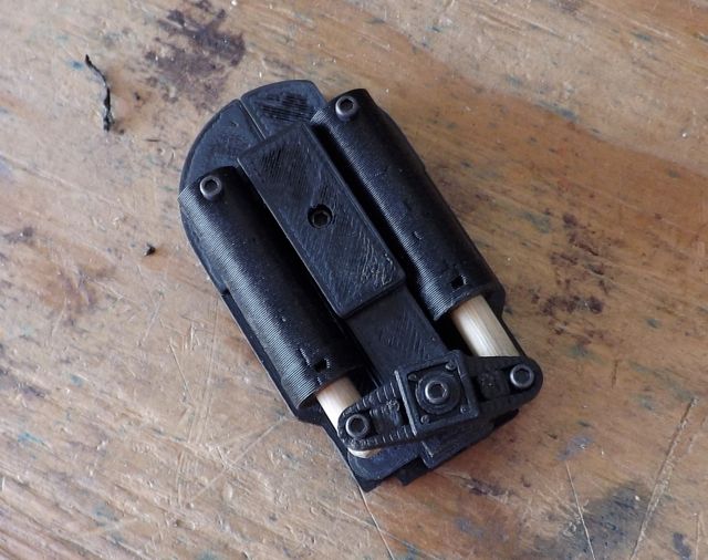
So with a new 3D model and my printer, I set out to resolve the design for Ed's knee and shocks. To be clear, I will machine a portion of this design for the final part. But while I'm figuring dimensions and mechanical linkages, I save myself tons of time and frustration and I end up with a much better product by using the 3D printer! So here's the eye candy:
These are the printed parts, true to the Horizon vinyl reference. The Chronicle pics revealed some inaccuracies in the Horizon version. I guess it's safe to say that the Horizon kit was not take directly from the movie prop. Even so, I think the overall dimensions of the Horizon kit are good. So onward with no loss of sleep...
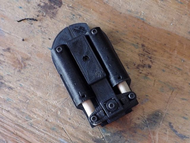
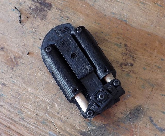
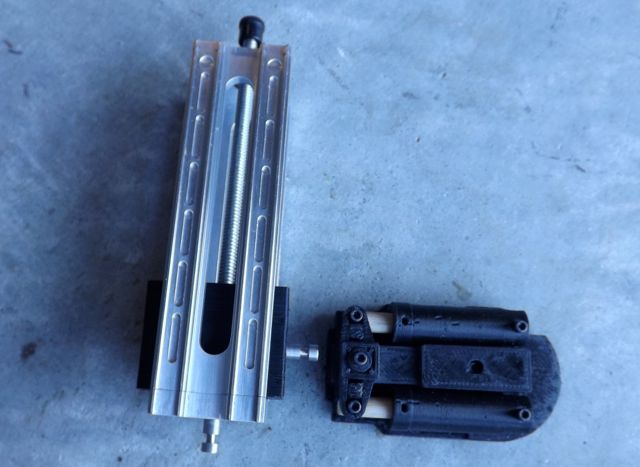
Here's the completed assembly with working shock absorbers!
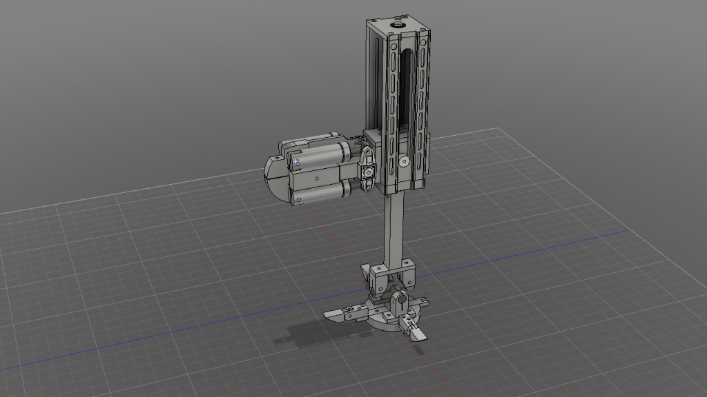
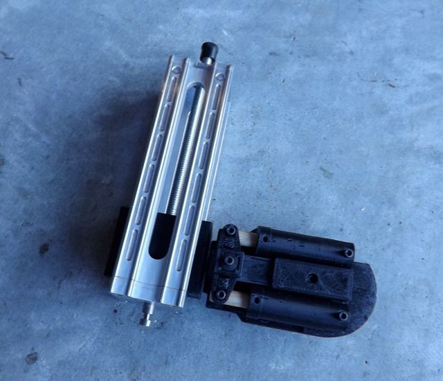
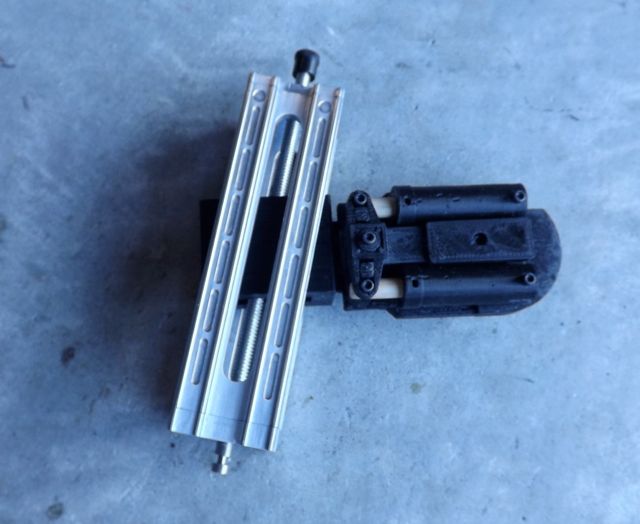
And here's the entire slide assembly mocked up:
And there you have it. I'll make steady progress for the foreseeable future. Of course, I'll keep this thread updated as regularly as possible. Thanks again to everyone for all the kind feedback. I really appreciate it!
A long time has passed with no updates. I had to take a break and handle life stuff. I see that there's been some discussion, though. That's great! I picked the ED back up this week. I'll reply to some of the comments and provide a build update.
I hope you find some of the photos on this li k usefull for your proyect which, I have to say, is a work of art and precission.
https://www.facebook.com/pages/Chronicle-Collectibles/1396578460601995?sk=photos_stream
Thanks for the link and the kind words! The Chronicle ED is fantastic. I suppose you can't get any more accurate than direct casts from the movie prop. The pics were extraordinarily helpful and very timely.
DEPUIS CE Que je ai trouvé après, je ai commencer à Fabriquer l'ED 209 Entièrement en aluminium
http://www.artmoviefan.net/t6114-robot-ed-209
I checked out your blog - your build is fantastic! Very impressive metal working skills. I wish I could read French. :cry
OK, here's where I am: Since my last update, I've been realizing the potential of the 3D printer. I can print nearly anything. It's really a huge asset in my tool set. With that, it's only as good as my 3D design. Up to this point, I've relied on Sketchup to design the ED209 armature. Sketchup has been great for what it is and it does it's job very well. But it does not export very cleanly to .stl format, which is the standard 3D printer file format. My model is also not a true solid model in Sketchup. This is the primary reason Sketchup does not export .stl files well. So, I've spent my downtime learning a new design tool - Autodesk Fusion 360. Fusion is a true parametric-based, solids modeling application. It exports to .stl VERY well. It's also free for the hobbyist. I'm sold. The process of re-design in Fusion forced me to evaluate some of my original assumptions about the dimensions and construction of the armature. I believe this model to be more accurate to the original. Again, the Chronicle pics were invaluable.
Here's my new model:

Another thing I did in my downtime was think about my approach to this build. Machining the parts has been a blast. It's my goal to use this build as a learning project, teaching myself to machine. So far it's been a successful journey towards that goal. One of the things I've learned,though, is that machining is a slow, laborious process where one mistake can scrap hours of hard work. This can be frustrating to say the least. I think I've found a better way.
With my 3D printer and new design, I have the ability to rapidly prototype parts and make assemblies much faster than machining them. As I'm working out the mechanics of an assembly, I can design in Fusion and send the design straight to my 3D printer. I can hold a working model in my hand in a fraction of the time it takes to machine the same model.
So with a new 3D model and my printer, I set out to resolve the design for Ed's knee and shocks. To be clear, I will machine a portion of this design for the final part. But while I'm figuring dimensions and mechanical linkages, I save myself tons of time and frustration and I end up with a much better product by using the 3D printer! So here's the eye candy:
These are the printed parts, true to the Horizon vinyl reference. The Chronicle pics revealed some inaccuracies in the Horizon version. I guess it's safe to say that the Horizon kit was not take directly from the movie prop. Even so, I think the overall dimensions of the Horizon kit are good. So onward with no loss of sleep...

Here's the completed assembly with working shock absorbers!


And here's the entire slide assembly mocked up:


And there you have it. I'll make steady progress for the foreseeable future. Of course, I'll keep this thread updated as regularly as possible. Thanks again to everyone for all the kind feedback. I really appreciate it!
") )
)