Anders Pedersen / Tip Top Workshop PKD blaster build

If it's not too much detail to ask - how did you get on with tapping all the holes for this? I've been finding I'm chewing up the first 2-3mm of the M3 holes before the thread starts to bite properly (on some practice pieces of resin). I've had a bit more luck starting a thread by just carefully screwing in an M3 bolt, but there is a fair amount of resistance and can imagine for a couple of the holes (especially the tube on the back of the bolt handle) there is a lot more risk of cracking the pieces by forcing a screw straight in.

Interested if there were specific taps/tools or advice you had that worked best?
The metal sighting rod will be a whole extra challenge later :)
I managed to tap most of the holes with no issues, though there were a couple I 'over-tapped' so the screws didn't bite properly when inserted. Where that happened, I filled the holes with JBWeld and re-drilled/tapped. I used a fairly cheap tap-and-die set that I've had for a while, bought off eBay - something like this one.

It's a really big help to have some light machine oil available; a drop of that in the hole before tapping, and again when the tap starts to 'stick', makes things much easier. That's pretty essential, I think.

I also found that tapping as far as you can go (until the tap starts sticking), then unscrewing the tap carefuly, thoroughly cleaning the hole of any swarf, and then gently screwing the tap into the just cut thread, allows you to go a bit further each time - in effect you're tapping the hole in a series of small increments rather than trying to do the full depth all at once.

Hope this helps. Good luck! :)

Thank you - slightly reassuring that a couple going astray isn't unheard of.
I'm probably not too far off on the process, and I've found doing larger (~M6 or M8 holes) pretty straightforward.
The M3 holes I wonder if I didn't clean out debris well enough between reinserting (mainly on the tap itself).

Thanks for the extra detail - half the fun of this kind of project is learning new skills.
 
I stupidly didn't take any 'in progress' photos of my ham-fisted wiring and soldering in the small confines of the magazine! Probably just as well. There was a lot of swearing. I did need to slightly Dremel out the inner part of the switch housing to get the switch I was using to protrude enough. It was easy enough to do but I had to go carefully as the space is very small and I didn't want to mess up the switch opening itself.

Anyway, the five LEDs and the switch and the battery were all eventually wired into place. I used the wiring layout suggested in Anders's instructions, which is a simple series circuit. The only change I made was to use a battery holder... just for ease of changing the battery eventually. I also added a 270 ohm resister between the battery and the switch, just to dim the LEDs a little as they were very bright at full power.

Once it was all working safely I fixed everything in place with hot glue, which has the added advantage of strengthening and insulating all the joints. Yes, I could have used heatshrink tubing, but I had run out, and ... reasons. Enjoy this photograph of the horrendously messy result which looks like a spider has indulged its most cherished halloween desires in there! It all works... that's the important thing.

View attachment 1505139 View attachment 1505140 View attachment 1505141 View attachment 1505142 View attachment 1505143 View attachment 1505144

Electronics done, all that remained was to attach the grips and the butt plate. I used slightly longer M3 bolts for the butt plate than those suggested (16mm rather than 12mm) just for added security.

View attachment 1505150 View attachment 1505151 View attachment 1505152 View attachment 1505153

And Deckard's blaster was complete! I'm really happy with how this ended up. I know it doesn't have all the functionality of a Tomenesuke or one of the other high end replicas. But the bolt action works, the cylinder works... it looks amazing, it's (as far as I can tell) really accurate... for a resin kit, I think it's absolutely fantastic! I think Anders Pedersen has done an incredible job and I'm filled with admiration at his skills and commitment.

I'd like to thank Anders, and also Tip Top Workshop for turning Anders's files into such a brilliant kit. I'm completely thrilled at what it enabled me to achieve. The kit is available here - Anders's Blade Runner Blaster 3D Resin Printed DIY Kit.

I have one of the old water guns that I converted a while ago into something that looks a bit like the 'worldcon' blaster. But this is a whole next level, and it's pretty much the blaster I've always wanted!

Here it is alongside my water gun conversion and an old solid resin casting that I painted up to look like one of the 'standard police issues'. I'll post some 'beauty shots in a following thread. Thanks again to Anders and Tip Top... and thanks to anyone who's read this far! :D

View attachment 1505154 View attachment 1505155
Hello, stunning build and you've inspired me to have a go. I ordered the kit from tip top but they said they didn't supply you with the bullets. Would you mind letting me know where you purchased t
I stupidly didn't take any 'in progress' photos of my ham-fisted wiring and soldering in the small confines of the magazine! Probably just as well. There was a lot of swearing. I did need to slightly Dremel out the inner part of the switch housing to get the switch I was using to protrude enough. It was easy enough to do but I had to go carefully as the space is very small and I didn't want to mess up the switch opening itself.

Anyway, the five LEDs and the switch and the battery were all eventually wired into place. I used the wiring layout suggested in Anders's instructions, which is a simple series circuit. The only change I made was to use a battery holder... just for ease of changing the battery eventually. I also added a 270 ohm resister between the battery and the switch, just to dim the LEDs a little as they were very bright at full power.

Once it was all working safely I fixed everything in place with hot glue, which has the added advantage of strengthening and insulating all the joints. Yes, I could have used heatshrink tubing, but I had run out, and ... reasons. Enjoy this photograph of the horrendously messy result which looks like a spider has indulged its most cherished halloween desires in there! It all works... that's the important thing.

View attachment 1505139 View attachment 1505140 View attachment 1505141 View attachment 1505142 View attachment 1505143 View attachment 1505144

Electronics done, all that remained was to attach the grips and the butt plate. I used slightly longer M3 bolts for the butt plate than those suggested (16mm rather than 12mm) just for added security.

View attachment 1505150 View attachment 1505151 View attachment 1505152 View attachment 1505153

And Deckard's blaster was complete! I'm really happy with how this ended up. I know it doesn't have all the functionality of a Tomenesuke or one of the other high end replicas. But the bolt action works, the cylinder works... it looks amazing, it's (as far as I can tell) really accurate... for a resin kit, I think it's absolutely fantastic! I think Anders Pedersen has done an incredible job and I'm filled with admiration at his skills and commitment.

I'd like to thank Anders, and also Tip Top Workshop for turning Anders's files into such a brilliant kit. I'm completely thrilled at what it enabled me to achieve. The kit is available here - Anders's Blade Runner Blaster 3D Resin Printed DIY Kit.

I have one of the old water guns that I converted a while ago into something that looks a bit like the 'worldcon' blaster. But this is a whole next level, and it's pretty much the blaster I've always wanted!

Here it is alongside my water gun conversion and an old solid resin casting that I painted up to look like one of the 'standard police issues'. I'll post some 'beauty shots in a following thread. Thanks again to Anders and Tip Top... and thanks to anyone who's read this far! :D

View attachment 1505154 View attachment 1505155
Hello. Stunning build and you've inspired me to order a kit from tip top but they said they didn't supply you with the bullets. Would you mind letting me know where you got them ?
 
Hello, stunning build and you've inspired me to have a go. I ordered the kit from tip top but they said they didn't supply you with the bullets. Would you mind letting me know where you purchased t

Hello. Stunning build and you've inspired me to order a kit from tip top but they said they didn't supply you with the bullets. Would you mind letting me know where you got them ?
Hi. Thanks so much for the comment, and congratulations on your TipTop blaster kit. You won't be disappointed, it's fantastic quality! To be honest, I'd forgotten that I did the bullets separately. Anders's original STL files on Thingiverse have separate bullet and casing models among them. I printed them in resin using my Elegoo Mars printer and put a length of threaded steel rod in each one to give them weight, as shown in the instructions. Of course, this means you will need access to a printer though. If not, I can only suggest seeing if you can get some dummy rounds, perhaps? I think they're fairly standard .44, as that was what the Charter Bulldog was (though can't swear to the exact dimensions). Hope this helps.
 
Hi. Thanks so much for the comment, and congratulations on your TipTop blaster kit. You won't be disappointed, it's fantastic quality! To be honest, I'd forgotten that I did the bullets separately. Anders's original STL files on Thingiverse have separate bullet and casing models among them. I printed them in resin using my Elegoo Mars printer and put a length of threaded steel rod in each one to give them weight, as shown in the instructions. Of course, this means you will need access to a printer though. If not, I can only suggest seeing if you can get some dummy rounds, perhaps? I think they're fairly standard .44, as that was what the Charter Bulldog was (though can't swear to the exact dimensions).
Thank you very much for your prompt reply. I'm looking forward to receiving the kit and starting the build process. If you happen to know anyone who's printing and selling the bullets please let me know.

Kind regards

Lee
 
Thank you very much for your prompt reply. I'm looking forward to receiving the kit and starting the build process. If you happen to know anyone who's printing and selling the bullets please let me know.

Kind regards

Lee
No problem. RPF member rgriesbeck makes a clear acrylic blaster stand that I think comes with a set of dummy bullets. Perhaps drop him a DM and see if he has any in stock at the moment. The project run thread is here. Good luck!

Edit: I should say that I don't know 100% for sure if his bullets will fit the Anders cylinder exactly as they are intended primarily for his own blaster kit, but I don't think they'll be far off.
 
If it's not too much detail to ask - how did you get on with tapping all the holes for this? I've been finding I'm chewing up the first 2-3mm of the M3 holes before the thread starts to bite properly (on some practice pieces of resin). I've had a bit more luck starting a thread by just carefully screwing in an M3 bolt, but there is a fair amount of resistance and can imagine for a couple of the holes (especially the tube on the back of the bolt handle) there is a lot more risk of cracking the pieces by forcing a screw straight in.

Interested if there were specific taps/tools or advice you had that worked best?
The metal sightinou
Hi. Thanks so much for the comment, and congratulations on your TipTop blaster kit. You won't be disappointed, it's fantastic quality! To be honest, I'd forgotten that I did the bullets separately. Anders's original STL files on Thingiverse have separate bullet and casing models among them. I printed them in resin using my Elegoo Mars printer and put a length of threaded steel rod in each one to give them weight, as shown in the instructions. Of course, this means you will need access to a printer though. If not, I can only suggest seeing if you can get some dummy rounds, perhaps? I think they're fairly standard .44, as that was what the Charter Bulldog was (though can't swear to the exact dimensions). Hope this helps.
Hi, I've received my kit and it's stunning. This is my first build and I wondered if I could pick your brains regarding the sanding. Did you sand every surface of each part or only selected bits? And also what grit from the first to last. Just reread your thread and I'll use it going forward. Regards
 
Hi, I've received my kit and it's stunning. This is my first build and I wondered if I could pick your brains regarding the sanding. Did you sand every surface of each part or only selected bits? And also what grit from the first to last. Just reread your thread and I'll use it going forward. Regards
Hi, and congratulations on getting your kit. You certainly won't be disappointed!

To be honest, the parts are so well printed/cast that I didn't have to do very much prep work in terms of cleaning them up. I just smoothed out any obvious imperfections and finished the larger flat surfaces to make sure that they were perfectly flat for the eventual paint.

One thing I did have to do was to check the fit of the parts that would move on the final piece - primarily the sliding bolt/bolt lever and the cylinder and its swing arm. The parts are designed with quite fine tolerances (which is a good thing as it means the prop feels nice and robust with no rattles). But this does mean that you have to do quite a bit of testing, checking, sanding and re-checking to ensure that these parts are going to move within or against each other without scraping or too much friction. The kit being resin it's important not to force these parts to do something they may not be quite ready to do! I found the areas that needed the most adjustment sanding were the back of the bolt, the bolt itself within the receiver, and the swing arm of the cylinder. It's just a matter of test-fitting, sanding a bit and testing again until the action of the mechanics feels 'right'. It's a bit repetitious and boring but it's worth it in the long run. Remember to allow for the thickness of the final paint, too, so the parts will need to feel a tiny bit 'looser' than they need to be when dry-fitted. When I came to assemble the gun I used graphite powder as a lubricant in all the places where surfaces slide past each other, and that made a huge difference.

I started out using 240 grit emory boards for the first pass. These are cheap as chips to buy in bulk and really useful. They tend to come double sided 180/240 grit. Once I was getting to the point where I was finishing rather than removing material I moved on to sanding sticks at about 600 grit and for the final finishing I wet-sanded using Micro-Mesh sanding pads from 1200 grit right up to about 4000 I think.

Before painting everything gets a final rub-down with a Scotchbrite or similar scouring pad, and then a final polish with a lint free cloth to make sure the surface is as smooth as possible for the primer. I also sometimes wet sand and 'scour'/polish between coats of primer just to iron out any minor imperfections that might have crept in.

Hope this helps. Good luck!
It helps loads. Many thanks for your detailed response
 
It helps loads. Many thanks for your detailed response
One more thing I thought of overnight regarding the 'sanding to fit' process. Towards the end of the process a good way of identifying which parts need fettling and exactly where is to give them a wipe over with a very slightly damp cloth to remove all traces of resin dust from the previous sanding and leave them a uniform colour. Then test fit them and try and get them to do what they're meant to do (without forcing them). When you take them apart again the exact areas that need further adjustment will be clearly visible as paler 'scrapes' or marks on both parts from the rubbing.
 
One more thing I thought of overnight regarding the 'sanding to fit' process. Towards the end of the process a good way of identifying which parts need fettling and exactly where is to give them a wipe over with a very slightly damp cloth to remove all traces of resin dust from the previous sanding and leave them a uniform colour. Then test fit them and try and get them to do what they're meant to do (without forcing them). When you take them apart again the exact areas that need further adjustment will be clearly visible as paler 'scrapes' or marks on both parts from the rubbing.
Makes perfect sense and I'll do that. Thanks again.
 
This thread was awesome in putting together my build. Thanks wayouteast for the details and photos! The thingiverse diagrams really didn’t explain everything from the tiptop kit and seeing your mods really helped guide me. I wasn’t given all the parts in terms of screws and pins so that was a fun troubleshoot. I had to use cut up paper clips to glue the bolt and lever together, haha. The main pins for the hammer and inner handle also were problematic cause they were too long and grinding them was a task. Ended up drilling some recessions in the amber grips for they have room.

I am left with two pieces I can’t figure out though, one looks like a mini cap of some sort and the other is just a mini rod. Nothing feels worse than having left overs, but what I don’t know can’t hurt me. Any ideas? Photo attached.

I am about 90% done, with only the electronics wiring and soldering to be completed.
 

Attachments

  • 98D6B785-E281-40AA-9B6D-B607110ECF6D.jpeg
    98D6B785-E281-40AA-9B6D-B607110ECF6D.jpeg
    1.4 MB · Views: 121
  • DF7269C5-6B69-4C90-B9D3-8DC56E87A6D2.jpeg
    DF7269C5-6B69-4C90-B9D3-8DC56E87A6D2.jpeg
    2.1 MB · Views: 122
  • 8995C07B-7167-49AE-9B8C-C049B36C8212.jpeg
    8995C07B-7167-49AE-9B8C-C049B36C8212.jpeg
    2.5 MB · Views: 112
This thread was awesome in putting together my build. Thanks wayouteast for the details and photos! The thingiverse diagrams really didn’t explain everything from the tiptop kit and seeing your mods really helped guide me. I wasn’t given all the parts in terms of screws and pins so that was a fun troubleshoot. I had to use cut up paper clips to glue the bolt and lever together, haha. The main pins for the hammer and inner handle also were problematic cause they were too long and grinding them was a task. Ended up drilling some recessions in the amber grips for they have room.

I am left with two pieces I can’t figure out though, one looks like a mini cap of some sort and the other is just a mini rod. Nothing feels worse than having left overs, but what I don’t know can’t hurt me. Any ideas? Photo attached.

I am about 90% done, with only the electronics wiring and soldering to be completed.
I am pretty sure the left one is a rounded cap for the hammer rod, with a hole for a ~2mm rod on the flat side?
If you are including a rod and spring inside the grips (not part of Anders original design from memory) similar to this https://preview.redd.it/inbr5opbfdu...bp&s=7eff467268dd906fa25aec1a8c911c5ba83696f9,
you would add your own metal rod and spring, with that little dome part then pressing against a recess in the back of the hammer.

The round end allows the contact point to pivot as the hammer rotates/moves, and the spring will press against the edges of the part you have in the photo.

The second piece... I'm not so sure. I assumed it was supposed to be an alternative pin for trigger/hammer but have not used.
Gotcha, yeah I ended up abandoning the rod and just installed the spring for posterity. I spent a decent amount of time trying to glue and attach it, and then realized you honestly can’t even see it through my grips, haha
 
Gotcha, yeah I ended up abandoning the rod and just installed the spring for posterity. I spent a decent amount of time trying to glue and attach it, and then realized you honestly can’t even see it through my grips, haha
That seems like a pretty reasonable option :)
That's a good shout on recessing the grips to give the pin through the hammer some room - still mucking around trying to get mine to fit.
 
This thread was awesome in putting together my build. Thanks wayouteast for the details and photos! The thingiverse diagrams really didn’t explain everything from the tiptop kit and seeing your mods really helped guide me. I wasn’t given all the parts in terms of screws and pins so that was a fun troubleshoot. I had to use cut up paper clips to glue the bolt and lever together, haha. The main pins for the hammer and inner handle also were problematic cause they were too long and grinding them was a task. Ended up drilling some recessions in the amber grips for they have room.

I am left with two pieces I can’t figure out though, one looks like a mini cap of some sort and the other is just a mini rod. Nothing feels worse than having left overs, but what I don’t know can’t hurt me. Any ideas? Photo attached.

I am about 90% done, with only the electronics wiring and soldering to be completed.
Congratulations on your build. It looks absolutely amazing! Beautiful weathering.

On the spare parts, Ekfud is right. The dome is exactly what he describes. If it's any consolation, I had to ask Dave at TipTop what it was! And I added a hammer rod/spring to mine, as you know. I don't know for sure what the little rod is - I didn't use it - but Ekfud 's conjecture sounds plausible.

Again, well done on the build. It's fantastic. :)
 
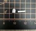
I used Hycote standard grey acrylic primer for all the parts (including the hardware for the receiver since I wanted that to be a darker steel than the standard stainless steel of the bolts and screws).

I did three light coats of primer, wet sanding between each one with finer and finer Micro Mesh pads. After the final coat the parts were given a polish with a lint free cloth and then left to cure for a couple of days. Note the extremely professional painting/drying set up I have in my 'shop' (upstairs room)! :lol:

View attachment 1505081

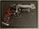
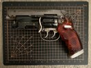
Once all the parts were fully cured they were ready for paint. I had decided on Alclad II metallic laquers for the final finish. I knew I wnanted this gun to be fairly pristine, as it would have been on set, so the finish needed to be as perfect as I could make it. After much experimenting with different metallics in the past, and several horrible disasters along the way, Alclad are paints I've had success with before and they're a known quantity for me now, and I'm fairly confident in them. The colours I'd decided on were: 'Steel' for the receiver and bolt lever and the switch on the receiver side; 'Stainless Steel' for the Bulldog frame, cylinder, cylinder pin switch, weaver knob, inner grip frame, barrel, triggers, hammer, trigger guard and other parts; and 'Polished Aluminum' for the bolt itself and the butt plate. The shells would be 'Polished Brass' and 'Copper'. There's also a tiny brass accent on the left front magazine cover. The magazine and magazine cover would be satin black. And the rear covers would be gloss black. The outer grip frame, as far as can tell from photos, is matte black on the flat surfaces and gloss black on its back and front edges (of course with the signature wear at the bottom from the grinding of the butt plate.

The Polished Aluminum, Polished Brass and Stainless Steel need to have a gloss black basecoat. And the Steel and Copper need a matte or satin basecoat. So all the parts were basecoated in either gloss or satin black, depending on their final finish, again using Hycote rattlecans. Painting went well, with only a couple of minor runs to deal with (easily, with a quick wet sand and recoat) and I was really happy with the results.

View attachment 1505082 View attachment 1505083 View attachment 1505084 View attachment 1505085

The edges of the amber grips were wet sanded to give a nice flush edge, polished and then given a couple of coats of Rustoleum Crystal Clear.

View attachment 1505086

Again, once touch dry, the parts were all set aside to cure for a couple of days before starting assembly - the bit I was most looking forward to!
Can I check on the grips. Did you wet and dry all over or just the backs and edges then just pray with the gloss?
 

Your message may be considered spam for the following reasons:

If you wish to reply despite these issues, check the box below before replying.
Be aware that malicious compliance may result in more severe penalties.
Back
Top