Thanks for the comment. Looked up the French which now makes me feel very cultured.Wow Searun
You are using an out of date browser. It may not display this or other websites correctly.
You should upgrade or use an alternative browser.
You should upgrade or use an alternative browser.
5 ft. ANH “Wooden” Falcon
- Thread starter Searun
- Start date
Been on vacation and attending to other commitments. Back working on the falcon.
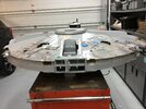
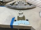
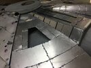
1. Thought it might be a good idea to show how it can readily be disassembled for those that might be interested. Maintenance is important when designing moveable features. These pictures are not glamour shots. Please forgive the roughness of the present basic status of the construction joints. They will be made pretty later.
2. I aluminum cladded the removable engine deck and have started locating some of the kit parts. This deck has some tight boundaries that are very unforgiving, While there is also a story on cutting plastic, far too many days were spent on “rearranging deck chairs on the Titanic.”
After constantly struggling with loose puzzle pieces, I noticed that the major greeblies in the three vertical tank deck and vent segments have a common trait. They literally link together at certain kit part intersections from the engine flaps to the turret ring. Plus, the upper vent circles touch each other. Once the center lane is set, the other two strings can be positioned to handle the horizontal edge dimensions which are also very critical. I used very thin aluminum base plates under key kit parts to facilitate constant adjustment. These three major strings are created as modules. Then the fun of locating major greeblies in between the gaps can begin.
3. Nothing is set permenantly. I have not even tried yet to position the many McLaren and Ferrari struts & tie rods. They will verify my puzzle work. Many more days are required, but the method described above helps In this complex area.
Attachments
-
 5CF31A59-C1BC-4B93-B6F2-B6AD65D1C774.jpeg916.8 KB · Views: 271
 -
 9CC5C923-4DB7-43E6-8527-329F168736F7.jpeg882.6 KB · Views: 258
 -
 4C5E5FE0-ABAF-456D-95DD-C4616BDE71C1.jpeg959.8 KB · Views: 248
 -
 9AD3A651-08AD-48F8-B9FD-1FE072E18854.jpeg892.9 KB · Views: 246
 -
 803D77D4-0771-405A-A3E5-821951510368.jpeg1.5 MB · Views: 281
Bjorn
Sr Member
Excellent work Searun!
Very interesting pictures showing how it comes apart.
As you have suggested, it really seems like there is not much room for incorrect placement with so many big pieces.
Those big pieces will fortunately guide you.
Keep in mind that you will need to sand the inside edges of the forward 3x vent rings as their diameters overlap where they touch.
Thanks Bjorn.
Also received a PM on this from the “Falcon Master” - - - eagle 1. He must have been up all last night. For what it’s worth, I never noticed this and had significant trouble getting kit parts to fit “between the ditches.” Checked my engine dimensions 10 times. They were spot on, which ironically caused the problem. Again geometry. The angle of the dangle strikes again. Same problem when your heading is off a bit flying or at sea.
This morning, things now fit much better. Still, this darn deck is tight. Another month or two of puzzle work required before the struts validate. But, what a relief!
Many, many thanks to you guys.
Searun
Which one is not like the other? I must not have not paid close enough attention in grade school. Jedi Veterans do pay attention.
DeAgo 2 ft. ESB Falcon obviously not equal to Bandai 1/72 Perfect Grade: ” It is known.”
But, even BPG 5 ft. ANH is not equal to 5 ft. Chronicles picture of ANH Studio Scale: ”You know nothing John Snow.”
DeAgo 2 ft. ESB Falcon obviously not equal to Bandai 1/72 Perfect Grade: ” It is known.”
But, even BPG 5 ft. ANH is not equal to 5 ft. Chronicles picture of ANH Studio Scale: ”You know nothing John Snow.”
t2sides
Master Member
Searun,
This is TRULY REMARKABLE how you are going about this. I am Blown Away every time I see your updates! This is such an original approach to building, yet it is yielding such an incredible amount of accuracy - but the coolest thing is, it's a metal Falcon!! You Sir are such an incredible, original talent!!! Keep up the GREAT work and awesome updates. Simply Amazing!
-Sean
Thanks Sean. The plan was to build an accurate aluminum clad model with landing gear and other moveable features with reasonable accuracy to the Studio Scale Falcon. The preciseness accomplished by you and others like eagle 1 is a bridge too far for me. But, I will do my best to follow the path of the falcon veterans. Details will take far longer than I first imagined. I remain in awe of the skill you guys have.
Last edited:
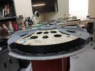
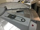
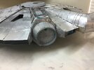
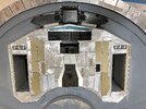
Here are a quick set of “naked“ falcon aluminum armor pictures. I have started on the starboard and port upper air lock passage way tubes.
1. Using the kit parts I have on hand and the long top rails helps with defining armor segments on the top and the sloping sides. Lot’s of duplicate greeblies required being discovered at this time.
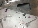
2. The modules of greeblies created previously on the engine deck that literally “hold hands”, have been removed. This helps me play around with where to locate hold down bolts as more kit parts are located from bags of greeblies. Note that the McLaren parts #40D & #10J are shown fixed on the very edges of the engine deck cover. Done properly, this greatly helped me position puzzle pieces in this very congested area. The trimming of the upper center vent rings, as advised by the expert’s comments on this web site was a significant help.
My sophomoric observation at this stage is worth clarifying. The many years spent by those that have built this studio scale model, let alone started kit part collection, map identification and begun construction is not fully appreciated until one starts and becomes more intimate with what is necessary. Although I have scratch build large models this size, what is needed to even reasonably replicate the 1977 ILM Falcon has been seriously under estimated by me. Those that have accomplished this, or have come close, certainly have earned respect.
1. Using the kit parts I have on hand and the long top rails helps with defining armor segments on the top and the sloping sides. Lot’s of duplicate greeblies required being discovered at this time.
2. The modules of greeblies created previously on the engine deck that literally “hold hands”, have been removed. This helps me play around with where to locate hold down bolts as more kit parts are located from bags of greeblies. Note that the McLaren parts #40D & #10J are shown fixed on the very edges of the engine deck cover. Done properly, this greatly helped me position puzzle pieces in this very congested area. The trimming of the upper center vent rings, as advised by the expert’s comments on this web site was a significant help.
My sophomoric observation at this stage is worth clarifying. The many years spent by those that have built this studio scale model, let alone started kit part collection, map identification and begun construction is not fully appreciated until one starts and becomes more intimate with what is necessary. Although I have scratch build large models this size, what is needed to even reasonably replicate the 1977 ILM Falcon has been seriously under estimated by me. Those that have accomplished this, or have come close, certainly have earned respect.
Attachments
joberg
Legendary Member
It's looking mighty fine from where I stand Searun I understand the complexities of that build; I'm not, mentally, ready to tackle that bird It's like seeing a painting from afar and saying to yourself: "That's seems simple enough"...until you go closer and you just realize, at that moment, that it's going to be an "Oh Crap" project all the way through
I understand the complexities of that build; I'm not, mentally, ready to tackle that bird It's like seeing a painting from afar and saying to yourself: "That's seems simple enough"...until you go closer and you just realize, at that moment, that it's going to be an "Oh Crap" project all the way throughThat is one Gnarly Falcon. Love the belt and braces metalwork. Maybe a Razorcrest next for that polished finish ?. Seriously though, nice work Searun.
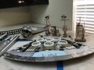
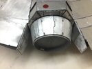
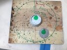
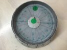
Took a break from kit part puzzle location and refocused on armor & experimenting with chips. Below are some pictures of the work on the circular air locks. I loved the “shield” patterns. Had to find a way to replicate the 360 degrees of uniqueness. Had to supplement the studio scale originals design given that my available pictures show just so much of the surface area.
After many tries with the micrometer measurements of base and top of the cone, I gave up on the left brain science project approach. Used ink dots on wood template for the base using the Bandai 1/72 scale Falcon cone. This then enabled simple ruler and straight line projection. For the top, a metal circle template for armor location was made by over laying the Bandai Falcon cone top. No measurement error. No math calculation. The shield pattern, in the plan view, of each of the 20 or so Port & Starboard shields involved connecting the hash marks projected on to the 5 ft. Model Hatch base & top by observing the unique shape of each. Yes, templates were then necessary by wrapping tracing paper around the cone pattern drafted on the model’s full sized hatch surface perimeter.
Wish I thought of this when doing the top disc armor segments instead of micrometer measurements. May use this lesson learned on the bottom.
Chips are an experiment in sizing and thickness. But, they add texture and are another clever design feature that seems to apply to science fiction spacecraft.
Attachments
Last edited:
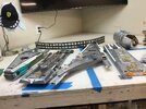
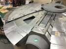
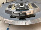
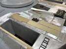
Flipped the saucer on it’s back to start some bottom skinning and armor placement on the main landing gear plateau. Major kit part layout on that area begins. Some of the greeblie panels appear to be on top of the armor based on “notch” nibbles between the segment lines. This seems to show up best on the Chronicles pictures.
Had to adjust layout from original to accommodate my retractable gear design since the size of ANH feet are wider than the studio scale wheel well door footprint.
Still adjusting greeblies locations to fit the as-built structure. Andre and his team did a great job in measurement on their drawings. Any real bust in variance is due to my construction “tolerance” , material thickness choice and eyesight when using a ruler. Over and over again, the kit parts let you know.
I-pad has problems. Hope cell phone pictures come out O.K.
Attachments
Love the overhead shot, and the other pics showing how deep the landing gear bays go. I cannot wait to see your landing gear installed.
I've taken to naming the areas that are unnamed with pet monikers, so the big Centurion tank hull cut into thirds (vertically and horizontally) that's aft of the landing gear bay box I call the "lower kludge factory" given how many nonstop greeblies it will have all over and around it.
She's definitely coming together!