1/350 Klingon Bird of Prey - Improving the AMT Kit

For a while I'd been wanting to redo the plating on the sides of the main hull. The more I'd looked at the studio model pics the more errors I could see in my previous work. I was convinced I could do a much better job now. For reference here are the finished shots of my first attempt at the side panels.
Side hull panels before.jpg


I started by removing these existing panels and smoothing out the surface. I then attached masking tape and drew the various shapes in to create a template. I took a lot more care and time than I had done initially making sure to also include the panels at the back tapered edge. I also marked out the positions of the button head screws you can see around the hull on the studio model.
PXL_20240530_212255058.jpg


Once I was happy with the sketched shapes I cut them from some 0.25mm styrene sheet and glued them in place.
They were then sanded back to make them a bit thinner and I added some additional detail pieces where needed.
PXL_20240601_092518721.jpg

PXL_20240601_092512323.jpg


You can see the partially completed starboard wing in the background which I was working on last year. I didn't take any progress shots of this as I wanted to figure everything out on one wing first rather than posting in progress shots of both wings. I'll share some detailed step-by-step shots when I get around to the port wing.

Back to the side hull panels and the button head screws. To recreate these I used some 1.25mm diameter styrene rod. The centre was punched using a pin which I'm now well practiced at as there are 6x screws each side. My first few attempts were well off though.
PXL_20240601_092745126.jpg


This was then drilled using a 0.45mm PCB drill bit in my pin vise. I found the method of punching with the pin first before drilling much more successful than just going straight in with the drill. I still ended up cutting the end off the rod and trying again many times though.
PXL_20240601_093355528.jpg


Now I had the hole in place, I rounded off the head of the rod, cut it off and glued in place on the model.
PXL_20240601_093922117.jpg
PXL_20240601_095231714.jpg


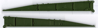
Here's a shot of the finished starboard side with all 'screws' in place. I've also added in the previous attempt for a comparison.
Before and After side panels.jpg


Now onto the port side...
PXL_20240605_164047502.jpg

PXL_20240605_164638028.jpg

PXL_20240609_161751744.jpg

PXL_20240609_161801691.jpg

...much better!
 
Back to the neck and some pieces I'd been very much looking forward to getting in place as the neck doesn't look right without them.
I'll call them the neck braces:
Neck braces reference.jpg


I started by creating a template shape from a piece of scrap mount board.
PXL_20240609_161714117.jpg


This was transferred to 0.5mm styrene sheet and cut out twice to form either side.
PXL_20240609_170139319.jpg

My cutting mat has a very rich patina!

I then cut some strips of styrene sheet in both 0.5mm and 0.25mm thicknesses to build up the inner edge where it attaches to the neck. See the below studio model image for ref.
Neck brace close up.jpg
PXL_20240610_134634819.jpg


I then worked on the lipped outer edges of these parts. Strips of 0.5x0.25mm styrene strip were cut and attached to masking tape. The tape was then stuck to the curve of the pieces making sure to butt the styrene strip up against the edge. This held it in place whilst I ran a brush loaded with plastic weld along the joints.
PXL_20240610_164903567.jpg


They were then sanded flush and tapered to match what I could see in the ref images. This was repeated for both the left and right sides.
PXL_20240610_164658862.jpg
PXL_20240611_170309576.jpg


In the black and white reference pic I could see what looks like 4 cross braces on the underside of these parts, it is a little unclear though. In that situation I've been looking at a studio scale replica I found online at this link. The details aren't 100% accurate on that model so I cross reference with the real studio model where possible.

To make the cross braces I started by marking their positions on the main piece.
PXL_20240612_084932743.jpg


The cross braces were cut from 0.75x0.25mm styrene strip. The strip was held down and a hole drilled at one end using a 0.4mm PCB drill bit in my rotary tool. This was then carved into a slot using the same drill bit.
PXL_20240612_090056939.jpg
PXL_20240612_090709722.jpg


I then cut and scraped notches either side on the neck brace for the drilled strip to sit into. This space was used to cut the strip to length before drilling the second slot and gluing the piece in place. This was then repeated for each of the three positions on both sides.
PXL_20240612_085508963.jpg
PXL_20240612_090942683.jpg


There is a brace at the curved end that follows the contour. I drilled a hole in the 0.75x0.25mm strip and then cut into it to form the shape.
PXL_20240612_093918909.jpg
PXL_20240612_094206037.jpg

For ref the gridlines on my cutting matt are 10mm squares.

The above piece was then glued onto the neck braces to finish them off.
PXL_20240612_094722905.jpg


I'm not sure how accurate these are to the real studio model due to a lack of ref, but they certainly look right to me.
Here's a shot of them glued in place on my model.
PXL_20240618_114646387.jpg
 
Last edited:
Whilst I was studying the studio model ref pics for the parts in the previous post, I noticed that the area shown below on my model was not quite right.
Above neck braces previous.jpg


The original kit parts follow the line of the neck, like the red line in the image below, so I'd originally recreated it this way.
It's hard to tell on the studio model images, but checking multiple views and comparing to the replica I linked earlier, I came to the conclusion it should follow the contours of the green outline instead.
Above neck braces should look like.jpg


In the image below you can see I've removed the three vertical bars and placed some stand offs. I've also cut the front part of the new neck profile and attached it.
PXL_20240613_155609860.jpg


The new pieces are made from 0.75mm styrene sheet, cut into a strip with a height matching the gap between the neck brace below, and the hump above. I mitred the cut by pushing a razor blade through the strip at an angle then refining on a sanding block.
PXL_20240613_155642943.jpg
PXL_20240613_155803955.jpg


The same was done for the side pieces but I also cut a bit from the top as per the reference images. You can see I've also added a strip on the right hand side. The length was cut following multiple test fits, shaving a bit more off each time until it was a perfect fit.
PXL_20240613_172553607.jpg


This was then attached to the front piece both sides as visible below. You can also see I've thinned out the trailing edge on the right where it meets the cloak strip as I want the appearance of thinner plating.
PXL_20240613_171615429.jpg


Here's how it looks with the hump installed and after trimming the excess from the angled front pieces so it was all flush.
PXL_20240613_174124259.jpg
PXL_20240613_174146382.jpg


Then I added the 3 vertical bars cut from 0.5x0.25mm strip either side and contoured them to match the ref (I later replaced the front 2 with 0.75x0.25mm strip as they didn't look wide enough, although this is not pictured). I also added some small circular indentations I could see in the ref using a 0.35mm drill bit. You can just about make them out in the pics below in the larger segment of the rear part of the side panels.
PXL_20240615_115513956.jpg
PXL_20240615_115649229.jpg

PXL_20240615_115549893.jpg


This looks much better now and the cloak strip continuing behind the side panels of the neck adds a nice layered depth to that area.
 
Last edited:
A note on this fantastic surgery you're doing- if it matters, the donors for the 'neck braces' don't have an arc to them. There's a 'break' to them, but the sides are completely straight (your ref is low-res, may be easier to read in the top view).
 
A note on this fantastic surgery you're doing- if it matters, the donors for the 'neck braces' don't have an arc to them. There's a 'break' to them, but the sides are completely straight (your ref is low-res, may be easier to read in the top view).
Thanks Clerval, I can totally see that now you've pointed it out. I've shaved a bit off the pointy end of those pieces now to make them a little more straight.

You mention the donor piece. Do you know which piece was used? Is there a thread somewhere identifying parts used a bit like the ones for the Millennium Falcon? Something like that would be a huge help to me with this project. Also if there were better res shots of the studio model. Despite a lot of web searching, the best I've been able to find are the ones on the Modeler's Miniatures & Magic site. Then its just screengrabs from the movies.
 
Here's the part, from the Revell Scissor Bridge. Part is 6mm thick, about 155 L and 21 W. All I know on the Trek era ships is what I've gathered from the era of kits, a lot of looking over the shots and my own kits, what was available to me as ref, and a bit from former colleagues at LFL. I'm building a Merchantman, and there's a lot of cross-over between most of the Trek III ships.
 

Attachments

  • mm_scBR_BoP.jpg
    mm_scBR_BoP.jpg
    866.4 KB · Views: 96
Here's the part, from the Revell Scissor Bridge. Part is 6mm thick, about 155 L and 21 W. All I know on the Trek era ships is what I've gathered from the era of kits, a lot of looking over the shots and my own kits, what was available to me as ref, and a bit from former colleagues at LFL. I'm building a Merchantman, and there's a lot of cross-over between most of the Trek III ships.
Thanks for the knowledge share and image Clerval. I'm now feeling tempted to have a go at redoing those parts.
If you come across any other donors used on the Bird of Prey it would be great to know.
Hope your Merchantman build is going well.
 
We’re there any disposable plastic razor bits used for the impulse?

I might be misremembering again
Interesting! I couldn't say for sure, possibly on the 3 ridges on top of the upper red section of the impulse engines? There's bound to be found objects as well as kit parts used in the models construction.
 
Here is some work I've done recently on the impulse engine parts supplied in the GS upgrade set.
I had a bit of a gap due to the modifications I've done to the rest of the engine area, so I cut a piece of 0.5mm styrene to fill this.
PXL_20240616_165950063.jpg


Whilst fitting the shim, I noticed that the lower clear resin part of the GS engines sticks out a long way compared to the studio model
PXL_20240616_172742004.jpg
impulse underbite.jpg


I marked a line in black pen about 2mm in from the end of the part and then sanded down to it on my belt sander.
PXL_20240616_173316614.jpg


I had to be really careful here as it would be very easy to put it out of square. I then tidied it up with a 600 grit wet sand on a sheet of nice flat acrylic. Once I was happy with this I test fitted and repeated the process until it looked right.
My intention is to rebuild the greeblies on this part at some point as they are very flat to account for the slimmer profile of the hull in the AMT kit.
PXL_20240616_212427818.jpg
PXL_20240616_212457929.jpg

In the second image above, you can also see a step I've introduced at the back of the lower impulse engine. This sat flush as stock from the GS set but I sanded the top, flat part of the resin piece to thin it down considerably. It helps to make it more accurate to the filming model.
I don't have pics of this sanding, it was done by hand with a sanding block rather than the belt sander. I needed to be very careful to keep it level.

Whilst working on those parts I noticed more gaps that will cause issues with light leak, so I added more styrene to fill them.
PXL_20240617_173755232.jpg
 
Following on from Clerval's help with the Scissor Bridge parts, I had a go at fixing the profile of the neck brace parts I'd made.
Ideally I'd like to remake the parts from scratch but after looking at them again, it was obvious that any attempt to remove the parts now would cause a lot of damage to the surrounding area. I'd need to work with what was already there instead.

I managed to refine the pointy end with a sanding block to make the profile more angular. See the comparison below (before is the 1st image, after is the 2nd).
PXL_20240618_114646387.jpg
PXL_20240624_103625829.jpg


I may also at some point try to refine the profile at the back end. I can't just sand it as there are lipped edges that follow the profile. Potentially the lips could be removed and the arced profile sanded flat. Originally the lips were attached as thin strips either side of the main brace (see top diagram in the image below). I could cut them off, refine the profile, cut a rebate and attach a single piece to form the lips again (bottom diagram in the image below).
Amendment to neck brace.jpg


I'm still undecided on this though as there are lots of details on the underside of the brace that may be ruined by this process. So potentially I'll be revisiting this at a later stage. For now though, more thought is needed.
 
Last edited:
This weekend I got a little more work done on the panelling details of the main hull. No work in progress pics were taken as it's all basic cutting of 0.25mm styrene sheet that I've shared lots before. I did need to do a bit of work to prep the hull first though so the pic below shows me scraping a #10 scalpel blade underneath the first layer of panelling. This was to create a more prominent step down for the second layer to fit into. I find this profile of blade really useful for this sort of work.
PXL_20240619_163146877.jpg


After lots of cutting, sanding back, failing, cutting again and building up of layers here's some pics of the 2nd layer of paneling:
PXL_20240624_103524442.jpg

PXL_20240624_103433780.jpg

PXL_20240624_103534007.jpg

PXL_20240624_103449584.jpg


I also did a little bit of work on the neck. I cut some wide strips of 0.75mm styrene sheet and filled the GS brass etch radiator parts under the neck. They have a hollow profile so adding the styrene gives them more substance. This also matches better to the studio model.
PXL_20240624_103349559.jpg


Some extra pipes were added between the radiators to busy the area up. Not screen accurate as I cannot find any images of this are. Just feels right to me.
PXL_20240624_103403066.jpg
 
Last edited:
I've been feeling like I need a bit of a break from working on the main hull so I've moved onto the wings.
As mentioned in a previous post I've already got the starboard one some way under construction, so I'll be starting on the port wing to catch it up.

Here's the Starboard wing underside and a list of the mods I've made so far.
Starboard Wing Underside.jpg

1. Removed this area completely and rebuilt using I beam profile styrene strips.
2. Removed these areas and replaced with stepped pieces made from layered 0.25mm styrene sheet.
3. Added various sizes of styrene strip to add detail as per reference images. Still lots more to add here and on the top side.
4. Removed the grooved element on the back of the wing from the original kit parts and replaced with one of my laser etched 'cloak strips'.
5. Removed the chunky details here and thinned out this portion of the wing. Detail will be added back later.
6. Hollowed this area out to add the circular 'cloak strip' detail seen in the below image, just behind and below the teardrop shaped gun mount.
Gun mount.jpg


And here's the Starboard wing top side and a list of the mods I've made so far.
Starboard Wing Top.jpg

7. The circular 'cloak strip', I'll show this in more detail below when I make it for the port wing
8. The wing tip is made up of 2 halves, the outer half has been replaced completely as I'll be remaking all it's details.
9. This detail piece has been re-profiled and had details added. The bottom half has not been finished.
10. It's my intention to remake the detail parts that go here completely. These white styrene plates are the base that I'll be adding details to.

So here is all the port side wing parts laid out prior to any modifications.
Top two pieces are the bottom (left) and top (right) halves of the main wing.
Below that are the two halves of the wing tip and gun mount.
The last pic on it's own is the detail piece that slots into the wedge shaped recess on the top half of the wing.
PXL_20240628_172515980.jpg

PXL_20230722_155741071.jpg
 
Last edited:
The first step was to remove the detail from the wedge shaped areas where the main wing joins the wingtip. This was done by chiseling away with a #10 scalpel blade, then scraping with the same blade and finally sanding with a home made sanding block (I cut rectangles of 4mm thick MDF and CA glue wet & dry sandpaper to it).

When I did this to the starboard wing it was an afterthought and I'd already glued the wing together. I thought it looked too chunky, then tried to do this with the drooped wingtip in the way which was really difficult. This time around I'm doing it before assembly.

PXL_20240628_172641392.jpg


In the image below you can see the starboard wing on top, which has been thinned down, and the port wing below which still needs to be. It's quite a difference. The stock parts are the same thickness right up to the point the wing bends which is not accurate to the studio model.
PXL_20240628_172755559.jpg


It's easier to get the correct thickness on the wing once the parts are glued together. Therefore I'm putting that part to one side for now and moving onto the I beam area at the rear inboard of the underside piece. I can't glue the two halves together until this has been done.

First job here is to cut away the chunky featureless strips on the kit part. This is done with nippers to start with and then refined with a scalpel blade. The 2 horizontal striped areas are also cut away as these will be replaced with more accurate stepped pieces.
PXL_20240628_174453019.jpg


The image below shows the side profile of the wings where they meet the hull. Here I've marked a rectangle on the underside of the port wing piece for removal. This is so I can insert a base plate for the I beams to be mounted to. You can see in the top (starboard) wing where this base has already been glued in place. You can also see the side of one of the I beams and stepped pieces.
PXL_20240628_181237876.jpg


I found in the model box that I'd already made the base plate piece a long time ago when I did the starboard side. This is a piece of 1mm and 0.75mm thick styrene sheet laminated together. This slots into the cut out area on the left side and underneath the area I'd removed earlier.
PXL_20240628_182611375.jpg
PXL_20240628_182855233.jpg


Next I'm going to glue the two main wing halves together. First though I need to grind away this block on the inside that is preventing the 2 halves meeting seamlessly. Not a problem on the stock parts but the added baseplate is getting in the way.
PXL_20240629_132535918.jpg
PXL_20240629_132843868.jpg


Here are the two halves glued together.
PXL_20240629_163027461.jpg


Dammit!!! I only remembered after gluing the halves together that I intended to cut this panel out and add a greeblie pit like on the studio model. That's going to be so much more tricky from the outside, totally meant to do it before gluing the wing together!
Dammit.jpg
 
Whilst the glue on two main wing halves was setting I moved onto the wingtip halves and adding more detail.
The domed area on the underside of the stock kit wing tip is totally solid. On the studio model it is hollow and you can see a ring of the same 'cloak strip' details that are on the backs of the wing and sides of the hull. Here's that pic again for ref.
Gun mount.jpg


To replicate this I first cut away the 'handle piece.
Handle.jpg


Next I cut away about 2mm of the dome. This is where the 'cloak strip' ring will be visible from the side.
PXL_20240629_135122083.jpg
PXL_20240629_141220299.jpg


Then I ground away the inside of the dome to make space for the ring. This also makes a finer, in scale edge to the dome.
PXL_20240629_141401845.jpg
PXL_20240629_142333004.jpg


To make the ring I cut a slice of a 14mm diameter styrene tube. This was then sanded smooth against a block for an even height. I then traced the inside diameter onto some 1mm styrene sheet in order to create a plug for one end. This is then glued in place and test fitted into the dome recess.
PXL_20240629_143426094.jpg
PXL_20240629_145701629.jpg
PXL_20240629_152022191.jpg


Next I glued the 'cloak strip' in place after carefully pre-shaping it around the barrel of a pen. This is necessary as the serrations between the segments are weak points prone to snapping. This is then mounted and glued into the dome recess.
PXL_20240629_152514463.jpg
PXL_20240629_153543665.jpg


Now that part is done I glued the underside of the wingtip into the main wing assembly. Apologies as I've missed a few steps of this in pictures. I first cut a strip of 1mm styrene and glued it on the upper surface (the opposite side of the image below), you can just see the corner of it jutting out over the green mat at the far left of the image. I then roughly trace around the wingtip shape on 1mm styrene sheet and cut this out.
PXL_20240629_170013436.jpg


I bevelled the edge of this panel where it will meet the overlapping top piece. Hopefully its a bit clearer in the second image.
PXL_20240629_170335723.jpg
PXL_20240629_170612130.jpg


The overlapping edges were then cut and sanded away.
PXL_20240629_175900940.jpg
PXL_20240702_155807608.jpg


I damaged the outer face slightly so this needed a few repair patches to be glued in. These will be sanded flush once set.
PXL_20240702_155821131.jpg
 
What's interesting is that when you're finished, the entirety of the original kit will be down to shaved bits of styrene all over the house, and you'll have an entirely new ship made of Plastruct, Evergeen, etc...
 
Back
Top