1/350 Klingon Bird of Prey - Improving the AMT Kit

Next up I replaced the curved brace parts that sit under the rear overhanging part of the upper bridge.
Neck brace.jpg


I'd ended up cutting these off to make it easier to build up the base structure of the neck.
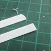
Firstly I held a piece of 0.5mm styrene sheet up against the model to mark the outline I needed. Here I've already cut the shape to fit against the curve of the lower bridge.
PXL_20230914_205846742.jpg


Both sides were cut, had the edges smoothed with a fine grit sandpaper and then were glued in place against the neck.
PXL_20230916_063018181.jpg

PXL_20230916_063031329.jpg


You can also see above where I've added some more detail to the underside of the neck. I wouldn't claim this to be accurate, it is the best I can do with the images I have plus artistic license to fill bare areas.
 
Here's a little more detailing on the shaft that runs along the underside of the neck.

There are two triangular beams that bridge the gap between the shaft and the underside of the neck.
Neck triangles.jpg

They look like they're made of U or I channel sections. It's missing entirely from the kit but Green Strawberry supply a photo etch part to replicate it in their set.

It is a double layered part, a mirror image folded over onto itself, but I felt it was still a bit thin. To fix this I laminated it to a piece of 0.25mm styrene sheet with CA glue and cut it flush by running a scalpel along the edges of the brass.
PXL_20230915_085049596.jpg
PXL_20230915_091002606.jpg


Here it is cleaned up and installed onto the rod. I've also added some small triangular struts at the apex of the triangles.
You may also notice a few extra details here that have been added to upgrade the resin part.
PXL_20230915_160940214.jpg


It's looking a lot busier under there now.
PXL_20230915_163715849.jpg
 
I'd been focusing on the neck area for quite a while so I needed a bit of a break from it.
I decided that now was the time to install my 'cloak strips' onto the sides of the hull. I'd wanted to get the base structure of the neck in place first as the strips fit around it.

I'd already removed the old detail in this area using a hooked chisel and a curved scalpel blade to scrape the plastic away inside the channel.
PXL_20230728_180614660.jpg
PXL_20230730_203808009.jpg


I'd previously glued some of the model parts here (the greebly pits on the underside of the 'hump' overhang) and since removed them causing some damage to the plastic lip above these strips.
Side lip damage.jpg


I decided it was best to cut this away and replace the lip entirely.
PXL_20230919_123546029.jpg


I also wanted to have a thin border strip running above and below the 'cloak strip' as is visible in the below studio model shot. I'd not allowed enough space for this so a rework was necessary.
Cloak strip detail.jpg


Once the lip was removed and filed flush with the channel I glued in some strips of 0.5mm thick styrene. This was necessary as I'd previously removed too much material making the channel too deep. You can see where I've marked with a red arrow that I also needed to add a few extra shims of styrene to keep the strip following the contour of the lower hull.
PXL_20230919_130531725.jpg


I then cut a thin strip of 0.5mm thick styrene which I formed to follow the shape of the channel and lower hull. The strip is cut wide enough that there is a slight overhang to create the lower border for the 'cloak strip'.
PXL_20230919_132901491.jpg


The strip was then glued in place with the etched 'cloak strip' butted up to it.
PXL_20230920_173946640.jpg


I then repeated these steps for the opposite side.
PXL_20230919_181938980.jpg

PXL_20230919_190243034.jpg

PXL_20230920_173927038.jpg

You can see in the above shot that I've also added a piece of the strip at the rear, framing the 'cloak strip' top and bottom.
I need this upper strip to continue all the way to the front but have to work out a few other details before that can be done.

This was a really satisfying moment as I'd put a lot of effort into developing the process to make these details on my laser.
I'm so pleased with the end result. Below is a little before and after comparison.
cloak strip before and after.jpg
 
Love the old school methods and attention to detail. We are blessed with more accurate models these days, but cursed as a lot of the fun was doing all this work! Great work, loving the progress. I wonder if there isn’t tank track at that scale you could use for the cloaking strip.
 
Love the old school methods and attention to detail. We are blessed with more accurate models these days, but cursed as a lot of the fun was doing all this work! Great work, loving the progress. I wonder if there isn’t tank track at that scale you could use for the cloaking strip.
Thanks Fett_Ish, its a journey I always enjoy. Would be way easier for me to get an SLA 3D printer, model and run out loads of upgrades but I just get too much enjoyment from cutting, shaving and gluing plastic this way!
Nice idea on the tank track, they're about 5mm high so there may be something out there in 1/144 scale that looks about right. I'm guessing ILM would have been using some kind of found item or model kit parts for the studio model.
 
Now I have the cloak strips around the sides of the hull I need to have them continue around the back between the engines.
Here's a shot of the studio model's engine area for ref.
Engine should look like this.jpg


The model kit has a few problems in this area. Firstly the red/yellow impulse engine emitter part is replicated as one piece without the channel through the middle. Below is a shot of the part as supplied in the kit, the yellow lines indicate where the gap should be.
PXL_20231016_094614902.jpg


This part and the kit as it is would be really difficult to modify to accommodate the channel. The gap through the clear part does not line up with the sides, it's much higher and far too thin. This is one of the main reasons I shelved the kit for so long.

The other issue is that the engine area is not really tall enough. This is partly due to the flattened tummy but the alterations I've done have made little difference to that.

Fortunately, the Green Strawberry kit contains some resin and PE parts that do a really good job of correcting this. Saves a huge amount of work for me too. Below is a shot of the resin upgrade for the central section that carries the cloak strip between the emitters. GS have understandably matched the look of the cloak strips from the kit though s so I'll upgrade the upgrade with my own.

PXL_20230816_174030387.jpg


First step was to remove material from the engine area on the kit to accommodate the resin. You can see the marker lines I put on to see how well the strips would line up with the engines. I distinctly remember feeling very disheartened after seeing how off it was and packing the kit away to be shelved. Glad I got back into it though!
PXL_20230805_172825441.jpg
PXL_20230805_173317187.jpg


I don't have many in progress shots of this process. I started with the abrasive wheel on my rotary tool to cut most of the material away. Then used a combo of side cutters, sanding sticks and files to refine it.

To replace the cloak strips in the resin part I used a hooked chisel, small file and scalpel. The brush is for clearing out the resin dust. The material is quite soft and brittle compared to the plastic so needs a lot of care. I did cause a bit of damage but nothing that can't be fixed or replaced.
PXL_20230816_175709104.jpg
PXL_20230818_215623895.jpg


Once the channels were clear I cut cloak strips to size from my laser etched version. These were then CA glued in with a piece of 0.25 x 0.75mm styrene strip either side to frame it.
PXL_20230901_150315050.jpg


Here's how it looks in place.
PXL_20231016_094810256.jpg


And here with the two clear resin emitter parts from the GS set.
PXL_20231016_094930578.jpg
Engine should look like this.jpg


There is still a bit of refinement needed with how the resin part fits into the kit's engine area. I may also need to thin down the lower emitter as it should not be as flush with the belly as seen in this pic.
PXL_20231016_094942091.jpg


That aside though it is looking light years ahead of the kit supplied parts.
 
Next I turned my attention to the upper surface of the neck. Here's a view of this area on the studio model for reference.
kg_kling_bop_studio_model-018.jpg


First I dry fitted the 'hump' and bridge parts so I could see how much of the neck would be visible. I roughly sketched the positions of the details in pencil to get the proportions right.
PXL_20230916_062943523.jpg


I started with the ridged strip in the centre of the neck. The grey area to the middle left of the studio model pic. Green Strawberry supply a photoetch part to replace this in their set but I found it to be too wide and the ridges were oversized.

Instead I counted the number of ridges and worked out how wide they and the gaps between them needed to be. I then drew up a striped vector image of the pattern on the computer to match. This was then etched on my laser into 0.25mm styrene sheet. The sheet was taped down onto a piece of ply to hold it in place and help with any bowing from the heat.
PXL_20230916_064530511.jpg


Here is the result of the etch after a couple of attempts.
PXL_20230916_065307086.jpg


I measured the width the strip needed to be including the two strips framing it and cut that from the etched sheet.
PXL_20230916_070534676.jpg

PXL_20230916_070730749.jpg


I was really happy with the result so I applied some Revell Contacta glue to the reverse and positioned the strip. I use Contacta as it has a bit of initial grab but with a small piece like this I can also still move it around. Once the position was set I ran some EMA Plastic Weld around the edges with a brush to lock it down.
PXL_20230916_071556837.jpg


I then started to layer up some of the rods and strips either side of the ridged strip. I paid careful attention to their relation to the ridges of the centre strip when viewing the reference images. Basically just counting the ridges back from the bridge so I knew where the strip should start.
PXL_20230916_075310052.jpg


The rods that go on next have a ring around them at the bridge end. To make this I took a 1.6mm dia styrene rod and drilled a 1mm hole into the end. I then cut thin slivers and gently rubbed them onto fine sandpaper until they were an even thickness. The bottom was then cut off so the ring was open on one side and I slipped them over a 1mm dia rod. This was then glued in place. Another two strips were also cut from 0.25mm styrene to go outside of these rods forming a step at the edge of the neck.
PXL_20230917_162209440.jpg
PXL_20230917_162246970.jpg


I then looked at the sides of the neck to make the panels marked in yellow in the below ref pic.
side panel.jpg


I'd worked out these needed to be around 6.5mm wide so I scored and cut a strip of 0.50mm styrene sheet.
The ends were then roughly cut with a razor blade and rounded into shape with a sanding stick.
PXL_20230917_162637572.jpg
PXL_20230917_164000907.jpg

PXL_20230917_164137528.jpg


These were then attached to the sides using the same method of Contacta glue first to get the position right and then Plastic Weld to lock them in place.
PXL_20230917_170721513.jpg


I also glued additional strips of styrene on top of the above ones at the main hull end. They were detailed with three thinner strips of styrene to replicate the detail you can see in the above ref pic under the hump overhang.
PXL_20230920_182203392.jpg
 

Attachments

  • PXL_20230917_163926598.jpg
    PXL_20230917_163926598.jpg
    730.5 KB · Views: 37
Last edited:
Here's a little more work on one of neck details; specifically this one.
Neck detail.jpg


There's one either side. The tricky part here is the two slots and how to get them consistently sized and spaced on both sides.
I started by marking the hole positions freehand with pencil, then trying to manually carve the slots with a micro drill bit in my rotary tool.
The results weren't great, I couldn't get the slots parallel or consistently sized. Especially not across 4 slots on 2 sides.

I had a rethink and decided to make a guide that I could run the drill bit through to position the holes. I drew a vector template for my laser and then cut it into a sheet of 1.5mm mirror acrylic scrap. You can see the 0.75mm styrene sheet I was drilling the slots into underneath the mirror acrylic. The laser cut holes in the mirror helped to keep consistent size, shape and angle. I just had to gently run the micro drill bit back and forth in the slot whilst it was running.
PXL_20230930_073559467.jpg
PXL_20230930_073726336.jpg


A ran lots of sets of slots and then picked the best ones. They still needed a little cleanup but were much better than my freehand attempts.
PXL_20230930_075428401.jpg


First job was to tidy up the holes a bit with a fresh scalpel blade. Then I marked the size of the panel and cut out the left and right piece.
To get the 'L' shaped profile I then stuck a piece of 1x1mm square rod to the back and trimmed off the excess..
PXL_20230930_083452392.jpg
PXL_20230930_084318768.jpg


I then started to shape the parts. I trimmed the back edge and rounded off with a sanding stick. Then held the pieces in my tweezers and scraped the top edge with a razor blade to make the bevels to the top face and front of the pieces.
PXL_20230930_102140141.jpg
PXL_20230930_105929420.jpg


They were then attached to the neck either side.
PXL_20230930_113902137.jpg
PXL_20230930_113913267.jpg

You can also see above some additional details I've added to those side panels from the previous post.
 
Last edited:
Yeah, though you should keep in mind that zip ties aren't truly ribbed. Their "ribs" are actually sawtooth in shape so that they catch the latching parts, so you'd need to pay attention to orientation and see which way looks best to you.
 
Well done Neon.
You have excellent scratch skills, perhaps in the future you could attempt an original project?
Thanks so much Carlb! My partner keeps encouraging me to do an original project too, it's definitely something I'd like to do at some point.
Another thing I'd really like to scratch build is the Hunter Chopper from the video game Half Life 2.
 

Your message may be considered spam for the following reasons:

If you wish to reply despite these issues, check the box below before replying.
Be aware that malicious compliance may result in more severe penalties.
Back
Top