Y-Wing (Gold Leader) Build - Nice-N Model Designs

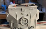
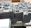
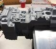
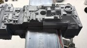
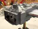
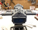
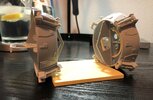
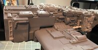
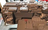
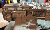
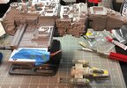
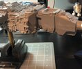
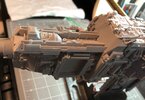
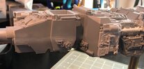
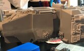
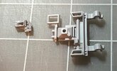
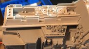
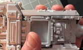
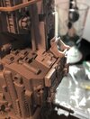
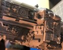
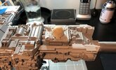
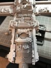
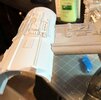
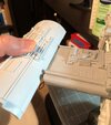
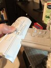
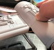
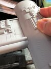
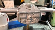
To attach the "frame" to the rear of the main fuselage, I used a small x-acto knife and some 220 to adjust it to fit, then used very tiny drops of Super glue to set it in place:
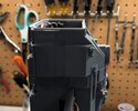
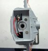
IMG_2153.JPG

IMG_2154.JPG

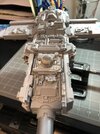
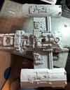
Top view:
IMG_2155.JPG

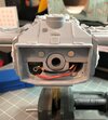
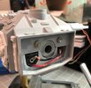
While the glue dries, I decide to test the lights with a new toggle switch that I ordered through All Electronics. The switch is the right style and size, but it will only handle up to 8 amps and the battery I'm using is 23 amps. I'm not an electrician, but I do know that if the battery amperage is too high, I will fry the switch. It's a problem I had with my R2 awhile back. As a result, I really want to test the switch before I start sealing the wires, etc. in more plastic and glue. I get the two, LEDs soldered in place, attach the switch and it looks good:
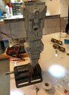
IMG_2156.JPG


I leave it on for a while, but the switch isn't getting hot which is a good sign. I'm thinking that because there are resistors attached to the LEDs, this may be preventing too much amperage from being drawn through the switch.

Another item I've been meaning to tackle is the gap between the two, top pieces:
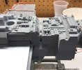
IMG_2157.JPG

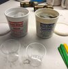
The gap is too wide for standard modelers putty, so I'm going to use some thing new, which Steve recommended in his Y-Wing directions: Magic Sculpt:
IMG_2158.JPG

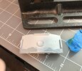
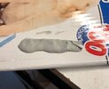
Like casting resin, there are a two parts, mixed equally by mass or weight. I was expecting something more liquid, but this is actually more like clay so it's easier to mix the two parts by hand. The final product becomes a light grey, piece of clay. I just roll it out on some wax treated card board, cut it out with a clay tool and then place it along the inside of the gap:
IMG_2160.JPG

Filling in the gap:

IMG_2159.JPG

Other side:
IMG_2161.JPG

I use another clay tool to flatten out the material within the gap.

Up next, cleaning up the main fuselage in preparation for attaching the wings and the detailed pieces.
 
Last edited:
After letting the Magic Sculpt set overnight, I use some Tamiya modelers putty to fill in the smaller gaps:

71CA7036-E3D3-4EE5-B94A-A6FBA2D503E2.jpeg

The Magic Sculpt hardens like a clay.
While I am at it, I fill in the lines between the frame and the rear end:

B5EF0AD5-F3CA-4BD0-941D-EC32AC3BBD40.jpeg

Up next, sanding and applying more putty. Painting and finally attaching parts.
 
How to I go about getting g one of these? I look online everywhere, even his website and I can't locate one. Any help is greatly appreciated. Thanks in advance.
-Josh
 
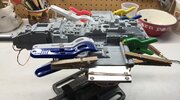
After applying a couple coats of putty, I am just about ready to start painting, but the top of the wings will need to be attached, first, so they are test fitted with some rubber bands.

I also test fit the rear hatch to make sure everything lines up correctly. Just a little more putty needs to be added to smooth out some of the lines:

CFBA28A5-EAE8-449C-B5D3-EB15E361F461.jpeg

The hatch is extremely thin near the top corners. So thin in fact that the resin is see through when placed in front of a light.
Adding resin could warp the piece and glue is too messy so I opt for putty.
Some thing I have learned over the years is to always sand down smooth surfaces before applying putty or glue:

399AD06C-EDBD-462C-8A80-BE42F3641E3F.jpeg

62ABAD7E-B550-47DA-BA1D-6638BB010201.jpeg

As with the hatch, the wings and sections of the body that will come into contact with the wings are sanded down and then applied with contact cement:

BEB5D03F-37C8-46AC-8F5C-5556B7507EB3.jpeg

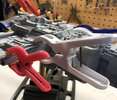
Clamps work better than the rubber bands. It’s nice to get some use out of these things. It’s important to get nice, clean lines. Otherwise it means more work later on.

D001377F-D0A8-4D7A-9E85-FD313DA4198E.jpeg

Coming up next, painting, more putty and adding the detailed parts.
 
Last edited:
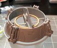
I hit the sides and the rear area with some Tamiya light grey primer and then filled in some of the uneven areas with putty:

IMG_2201.JPG

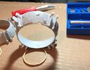
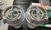
I left the main fuselage alone to dry in the cold garage and get started on the engine rings in my nice, warm office. :D

IMG_2206.JPG

First thing to do with these it add the "battle damage" to the right ring. Luckily, there's already an indentation built into the part, so it's just a matter of following the lines and then using a reference of the original. Using a new X-acto knife blade doesn't hurt either. :)

IMG_2207.JPG

The next step is to place the "shock" parts on the sides of the rings. I used some contact cement because some of these don't fit snug enough and need to be moved around a bit before final placement:
IMG_2208.JPG

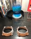
Nothing like a blue cocktail to go with Y-Wing building.
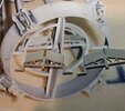
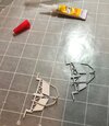
Following the directions, the next step is to tackle the "steering assemblies" which are made up of these "fins".
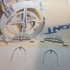
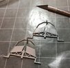
Looking at the reference photos, the fins are actually angled on both sides and these parts are completely straight, so they have to be modified. Here's a side by side photo:

IMG_2210.JPG

I used the reference photo and the small, spindly part as a reference to create the angles with a small x-acto knife.
To place the part, the fin needs to be cut at a specific angle. I used a large x-acto knife to remove most of the resin and then the smaller knife to cut out the smaller details:

IMG_2211.JPG

Now, we finally get a chance to use the Super glue. Because these parts are so small, this is the perfect application. It's going to be easier to start with one side first, let it dry and then on to the other side. I glue the parts on a sheet of wax paper to keep them from sticking to my mat:

IMG_2212.JPG

Once dry, the other side of the parts are attached with a little help from a small x-acto knife to keep the spindly pieces in place:

IMG_2213.JPG

The key to putting these together is patience. Time for break to let every thing set.

Lots of work accomplished today, but the good news is that because this is such a large model, sections of it can be worked on while other sections can be set aside to dry.

Up next, finishing off the engine ring steering assemblies and finally, adding those wonderful details to the main fuselage.
I can hardly wait.
1608510305261.png
:)
 
Last edited:
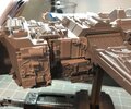
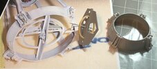
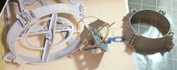
To complete the "steering assemblies", I took the resin rings I had machined and cut them in half, using my cutting mat as a reference.
I then trimmed the ends so that they were completely flat and test fitted them. The large "fins" with the holes (Sea lab parts? They remind me of the Seaview or Tomorrowland structural parts) have very tiny holes near either end which can be used as a reference for placing the half circles. The ends of the half circles rest against the beam or frame of the fin parts. Each half circle should line up perfectly with the other half, suggesting at a complete circle, running through the fins.

Here's a photo before attaching them inside of the engine steering rings. The parts near the bottom of the photo are for the starboard or right side of the Y-Wing:

IMG_2214.JPG

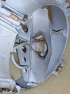
Some thing I neglected to pay attention to was the fact that the end of the large fin pointing outward has unique edges. One edge is straight, while the other has an added angle or notch. After carefully going through the photos in the directions and the reference photos last night, I finally realized that this notch should be facing the bottom of the ring, as does the "hook" on the other end of the assembly. Unfortunately, the directions don't cover this and it's very hard to tell from photos where the notches and the hooks are. In fact, even the reference photo below is deceiving, because it was taken while the model was flipped upside down, but this was the best photo I could find for a reference, so I studied it carefully while fitting the parts. Note that the "battle damage" near the top of the part along with the straight end of the large fin as it sticks out of the large engine steering ring:

Bottom Right Engine Closeup.jpg

And here's the parts for the port or left side. Note that the reference photo is of the port side from top to bottom (Not flipped upside down):

IMG_2215.JPG

IMG_2216.JPG

To help with the placement of the steering assemblies, there are large and small notches within the rings. I had to modify some of the large notches to help with the placement of the assemblies. They simply weren't sticking out enough. The assemblies were also trimmed a bit on the edges to help with the placement. I used super glue for the parts and finished the smaller piece with contact cement because one of them wasn't touching the ring. I used rubber bands to help keep the smaller "legs" in place while the cement dried:

IMG_2218.JPG

Up next, finishing the assemblies.
 
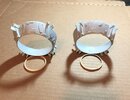
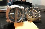
After letting them set over night, then removing the rubber bands and tooth picks, the steering assemblies with rings are complete.
The one on the left is for the Starboard engine:

IMG_2226.JPG

Here is a side view to show off the position of the "handle bar" part:

IMG_2225.JPG

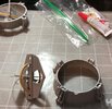
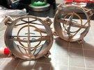
I used a couple of cups to help level the steering assemblies while adding the detailed pieces:

IMG_2317.JPG

Port top side:

IMG_2318.JPG

Up next, attaching the detailed pieces to the main fuselage. :)
 
Last edited:
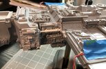
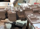
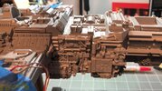
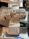
Following the directions, we start with the Port or Left side, near the top of the wing. It's basically a blank canvas:

Port Side - Blank.JPG

I start with the two panels. As usual, I use some 220 grit on the panels and on the body of the fuselage before applying Super glue:


Port Side - Part 1.JPG

With the panel in place, I cut down the pipe piece along with the smaller piece. The rectangular part actually had to be cut in half and then trimmed.
The instructions have a couple of really good photos of this section, but I also heavily used one reference photo of this area for the placement of the "pipes":

IMG_2230.JPG

And with those parts in place, we're done with the port side in front of the wing. Here's a forward shot of the same area. I couldn't find a good reference photo of this angle, so I simply used the photo from the instructions:

IMG_2231.JPG

Next is the Starboard or right side, near the top of the wing. Again, we have a "blank canvas" of sorts:

Starboard Side - Blank.JPG

As with the other side, I started with the panels and then added the small parts.
A very small part that goes on the edge of the wing needed to be lengthened, so this section isn't quite done just yet:

Starboard Side - Mostly finished.JPG

Here is a forward shot, featuring a small detail that had to be cut out of one of the panels:

IMG_2229.JPG

The final, small detail was lengthened. Judging from the reference photos, the rectangular area has a length that is twice the size of it's width.
Although the instructions have a very good photo of this part in place, I used a reference photo to help with the placement:

IMG_2261.JPG

One more small, detailed piece needs to be added near the middle panel.
After looking more closely at a couple of reference photos, I decided to remove and reset the center panel and the small, rectangular piece:

Top Starboard Side Part 3.JPG

Unfortunately, the small, square part that is needed to finish this section wasn't included, but I am able to put it together by cannibalizing two extra parts:

IMG_2283.JPG

A small, square section of the larger panel was cut out and then a notch had to be made on the surface, near the center to get it to fit just under the pipe. Here it is attached:

IMG_2285.JPG

And with that last part is in place, the Starboard (right) side is done.

Moving on with the directions, the Y-Wing gets flipped over to start work on the bottom, Starboard side.
Actually, I forgot to take a photo before I started adding parts, so here I've already added the small panel with the small, half round details and the square piece that fits over and around the mounting hole. Note the length of the half round section of the small, rectangular, flat panel part near the middle of the photo:

Bottom Starboard - Blank.JPG

To add the largest panel, it had to be trimmed a bit on either side to get it to fit.
Some thing I didn't realize initially is that the small, rectangular panel with the half circle needed to be trimmed about 1/8" before fitting the circular detail. I've circled the area below:

Bottom Starboard Complete2.jpg
 
Last edited:
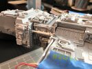
Continuing with the aft section behind the wing, this is the Port or left side:
IMG_2232.JPG

Both of the details that go here have to be modified. The panel actually needs to be shortened on all sides. I use my handy belt sander to do the job:
IMG_2233.JPG

Done:
IMG_2258.JPG

Now on to the details that go under the wing. The piece gets flipped over (still the Port side) so the detailed pieces can be added:

IMG_2235.JPG

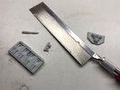
The large panel that goes into this area, below the wing has been cast with some detailed parts on it's edge, so I remove these with an artists saw and then use the belt sander to completely clean/level off the same area:

IMG_2236.JPG

The smaller panel is attached. I notice a problem with a bubble hole on a detail piece on the wing, so it's filled with modelers putty. I'll put this area on hold until the putty is dry:

InkedIMG_2259_LI.jpg

With the detailed part (oxygen tank) sanded down and cleaned up, I was able to get the detailed panel installed today.
Accept for some pipping, that should do it for the bottom of the port side:

Bottom Port Side Finished.JPG
 
Last edited:
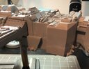
Ironically, my Y-Wing ornament fell off the tree and since I had some Super glue handy, I decided to work on it at the same time:

IMG_2237.JPG

While waiting for the port side to dry, I move on to the Starboard, forward area:

IMG_2248.JPG

Following the instructions, these two pieces need to be flattened down and then glued together:


IMG_2249.JPG

I use a large x-acto knife, a belt sander and some 220 grit to flatten them down. Then I wash the parts in warm water with a little dish detergeant.
I double check a couple of reference photos and then super glue them together:


IMG_2250.JPG

It's easier to glue this part to the fuselage while it's on one side:

IMG_2251.JPG
 
Now on to the Port side, forward section:

IMG_2252.JPG

According to the directions, the two, detailed pieces near the bottom need to be removed and relocated, lower.
I use a very sharp, large X-acto knife to accomplish this. It's take a lot of wiggling to finally cut off the two, tiny pieces.
Once removed, I clean up the area a bit:


IMG_2254.JPG

An extra, detail part was included and since it's cleaner than the original, I decide to cut it out and use it.
I checked for the smaller, square part, but I didn't find it. It's so small, I don't think it's going to make much difference:

IMG_2255.JPG

I don't want to place these small, detailed parts in the wrong place, so I use the long, rectangular part as a reference for the placement.
Rather than remove the parts to apply the glue, they're simply left in place and the glue is added to the corners. The pieces are so small that the glue runs underneath them:

IMG_2256.JPG

The next step is to flatten the long, rectangular part along with a small panel to get it to fit on the side of the forward fuselage.
I checked a reference photo that displays a top view of this area and realize that the panel is too short, but an extra panel is included, so I decide to cut down the second panel and attach it to the first one. Here they are, side by side:

IMG_2253.JPG

And put together:

IMG_2265.JPG

Top view:
IMG_2266.JPG

I filled in the indentations with putty and then do a test fit:

IMG_2278.JPG

It looks good, but I notice that there is a good size hole between the part and the main body. I check through the photos in the directions and the reference photos. There is a part that goes into this corner, but it was missed within the instructions at this point and wasn't included with my kit. Here's the part:

IMG_2280.JPG

I double checked all my reference photos and the instructions, but this part doesn't appear any where else on the model. It resembles a Mouse droid to me. In any case, it won't fit as is and basically needs to be streamline with a X-acto knife:

IMG_2281.JPG

Here it is in place:

IMG_2282.JPG

While waiting for the panels to dry, I move on to the additional details on the port side which include a small, square panel and a Kettenkrad part.
The instructions call for the part to be positioned at an angle against the 8-rad neck piece. I checked the reference photos and it is centered very close to the 8-rad part:

IMG_2274.JPG

But, looking at several reference photos, including the ones on the Starboard and top side, show this part as sitting flat, so it appears that this part was cut down a bit. In this top view photo, there is a small piece sticking out of the back. I simply cut this part off, making the entire piece flat.


IMG_2275.JPG

It seems to make sense if the original model guys wanted to get the part to sit flat and well attached:

IMG_2276.JPG

Because the same parts are attached on the other side in similar positions, I just go back to the Starboard side and basically do the same thing:

Starboard Side Forward Updated.JPG
 
Last edited:
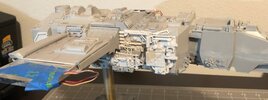
The instructions call for a small, hammer shaped part to be glued in an empty area on the Port side, but I'm not seeing this one in any of the reference photos. Does any one know if this is correct?
Port Side Detail Question.jpg

Here's the reference photo:
Left Side - Neck.jpg

Here is how my Port side is looking so far:
Port Side Forward Updated.JPG
 
Last edited:
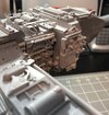
With the all of the details on the fuselage now in place, the only area left is the top.
The largest piece that needs to be worked on is the Astromech panel or holding bay.
The part is cast in a very thin piece of resin, so it's easy to score it with a X-acto knife:


IMG_2288.JPG

The panel sits on top of a recessed square that hold the R2 in place:

IMG_2289.JPG

Next up, modifying the R2 into an earlier "ILM" version and detailing the Astromech bay.
 
The "Astromech bay" is ready to go. To give it some depth, I added modelers putty inside of it:

IMG_2308.JPG

Here it is, installed. It will need to be blended into the rest of the fuselage:
IMG_2309.JPG

And here it is with the modified, ILM R2. In some references photo he's lower in the bay, while in others he is higher:

IMG_2310.JPG

Last weekend I spent the afternoon cleaning up the tiniest of the parts while watching a football game. These will go on top of the fuselage
(Notice the round "plug" part near the top of the photo. The piece with the crosses on it can be found on the wings of the TIE Fighter model):

IMG_2311.JPG

I start out by adding some small parts near and around the Astromech bay part:

IMG_2312.JPG
 
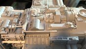
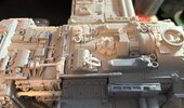
Continuing with the top detail (moving from the bow to the stern/rear), I've added more, tiny parts. Most of these are in white or a light grey:

IMG_2313.JPG

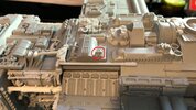
There were a couple of differences I found between the photos within the instructions and some reference photos. Because a couple of parts act as "plugs" or "covers" for electronic connections, these parts were either missing from reference photos or were turned around, probably because they were removed/replaced during filming, photography, etc. After looking at some production references, I positioned them this way:

InkedInkedIMG_2313_LI.jpg

The rectangular part was rotated 90 degrees and cut down slightly in the instructions photo. I found a couple of reference photos that shows it positioned this way. The circular part was rotated 180 degrees in the instructions photo, but most of the reference photos show it in this position.

The part circled in red is what is shown in the instructions, but unfortunately, it's the wrong part. The overall shape is correct, but the detail is different. What's interesting about this part is that it does reside on the right side, near the lower, middle section, so two of these parts were used. Two of the other version were also used, near the center of the top and on the left wing.

One more part that needed to be placed turned out be actually be a replacement. Here's the area that needed to be modified:

InkedIMG_2314_LI.jpg

I'm not sure where this part came from. I checked the Red Jammer photos, but it's not on that version, so this could be a mistake, unless it exists on Gold 2, Gold 3, etc. Luckily, it's easy enough to remove with a good size X-Acto knife:

IMG_2315.JPG

And here it is with the detailed part in place:

IMG_2316.JPG

I checked several reference photos and it looks like piping actually gets tucked under either side of this part. The placement as seen in the instructions is spot on.
There is one last, detailed piece that needs to be added, but because it is connected to a pipe, I'm going to save it for later.

So this covers the instructions for all of the detailed parts on the main fuselage for Gold Leader. There are some details needed for the bottom of the neck where it meets the cockpit section, but that comes later.

Up next, the engines which include wiring up the LEDs. Fun, fun, fun. :)
 
Last edited:
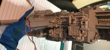
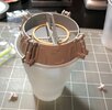
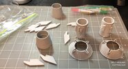
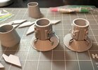
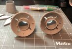
Time to assemble the engine thrusters:

IMG_2319.JPG

The parts are already cleaned up and ready to go. Before the gluing begins, I go over the fine detail on the cylinder pieces with some small x-acto knives.

The cylinders should sit flat with the shrouds. I make sure they line up as per the instructions and then check a couple of reference photos. Unfortunately, there aren't a lot of good photos of these parts on Gold Leader, but from what I found they do match what is specified in the instructions. As per the instruction photos, these are (from left to right) the starboard and port top sides. I used the thicker line on the shrouds as a marker for the top of both parts. As usual, the parts are sanded slightly and then I used a little contact cement. One reason is because I want to make sure that the cylinders are centered once the "fins" are added. They might move around a little while each fin is added:
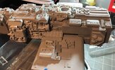
IMG_2320.JPG

To make the assembly easier, I mark the bottom of each part so that they are lined up properly and to help identify which is right (Starboard) and which is left (Port):


IMG_2322.JPG

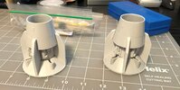
I use super glue to attach the "fins". Because the "thruster cups" are angled, they need to be placed first with the fins around them:
IMG_2324.JPG

After letting them dry, I check the instruction and reference photos to make sure the cups are properly placed.
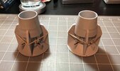
Then I use very small dabs of super glue gel on the end of a tooth pick to get between the fins and the "cups".
Rubber bands help keep the "fins" in place:

IMG_2325.JPG

Up next, detailing/cleaning up the main fuselage and finishing the thrusters.
 
Due to some bad weather, I wasn't able to get into my workshop and machine the parts for the thrusters, so I'm putting them on hold until possibly next week.
So with the build of the thrusters and engine tail assemblies complete, the instructions for Gold Leader abruptly end.
The good news is that the Red Leader instructions details most of what is left, so I'm putting down one set of instructions and picking up the old set to finish this model off.
Since the main fuselage is about 99% done, I'm going to move on to the engines and the Red Leader instructions are very detailed about these.
The first item I'm going to tackle is attaching the engines. Something I think that was missed in the Gold Leader instructions was a minor modification needed on the engines themselves. Here's the left (port) engine:

IMG_2364.JPG

There is a gap between the engine and the wing, caused by some "ribbing" detail. I used a small x-acto knife to scribe an arc around the large pipe and then remove the detail:

IMG_2365.JPG

Now the gap is removed:
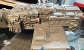
IMG_2366.JPG

The Starboard or right side needed more resin to be removed:
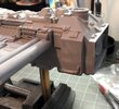

IMG_2372.JPG

But the end result is nice:

IMG_2373.JPG

I need to let some JBWeld set on the engines before I can move forward with these guys, so I'm going to finish up some misc. items next.
 
I need to add some earth magnets to the rear hatch.
Magnets have already been added to the main fuselage. In fact, these are left overs from my SS TIE. I used the same magnets for the wing panels, so they had to be extremely small:

IMG_2367.JPG

Rear panel:
IMG_2368.JPG

Two magnets are attached and then sanded down lightly. I'm going to try some new, gel Super glue to help fill in any gaps between the magnets and the panel:

IMG_2369.JPG

I also sand the upper section of the panel and then press it in place for about 25 seconds:

IMG_2371.JPG

The next misc. item is a small detail for the tail, steering assemblies.
There are very few references for these little guys, so I used the photo within the instructions to place them.
As in the photo, this is a shot of the tops of both assemblies. The small details have a "button" on one side and they appear to be facing each other.
Just for grins, I used a little super glue gel to keep them in place:

IMG_2370.JPG

The tail assembles are completely done at this point.
 
Tonight I'm going to finish attaching the main part of the engines. One of the nice features of the latest Gold Leader kit is that the top half of the engines has a built in platform for attaching the metal armature wing, so it's just a matter of drilling some holes into the resin platform and then installing some screws.
The instructions for the Red Leader kit only call for contact cement but four bolts will make sure these babies won't come off any time soon. :)

One of the trick to installing bolts, is that the main fuselage needs to be flipped upside down, so here's the bottom of the model:

IMG_2375.JPG

After making sure everything is lined up correctly, I sanded down the resin platforms and the aluminum bar before applying some contact cement. I also added a small drop of cement to each bolts before tightening them up.

And here's a top side shot:

IMG_2376.JPG

Up next, finishing up the engines and finally getting the lights attached.
 

Your message may be considered spam for the following reasons:

If you wish to reply despite these issues, check the box below before replying.
Be aware that malicious compliance may result in more severe penalties.
Back
Top