Tron Legacy Daft Punk Thomas Helmet simple light up project

colonelmasako

Active Member
Tron Legacy Daft Punk helmet mod using LED strips

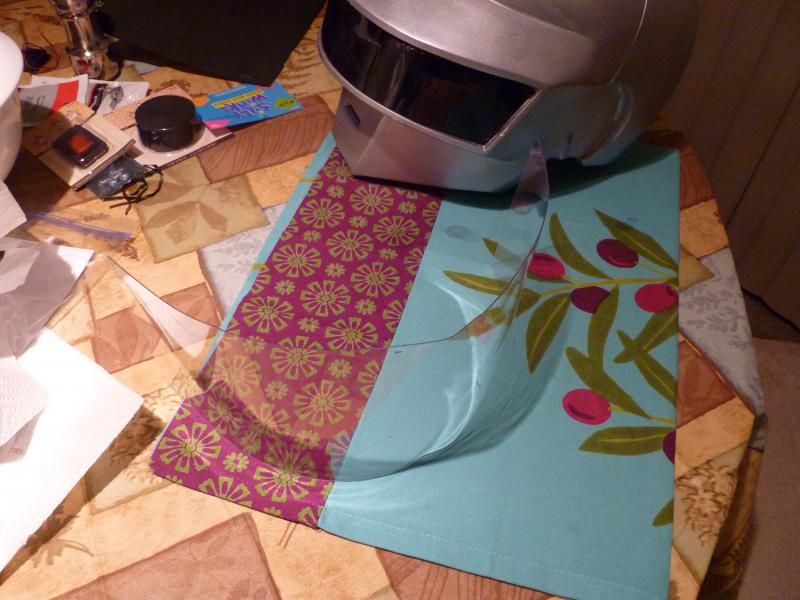
This thread should be pretty quick. Showing WIP of an LED light rig I'm designing for my client. First picture shows all the parts ready to go.


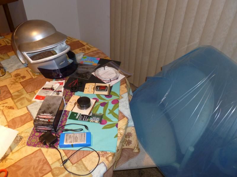
The client sent me his helmet and the visor. The blue stuff is the PETG I had left over from another project. Other parts to be showcased with progress.

1. Install visor

This was tricky from the get go because the helmet came to me slightly warped. I swear these helmets do this all the freaking time....my other helmet came to me warped. Are they really so sensitive to temperature? As a result I had to trim the visor down about 1/4" to make it fit in the gap.


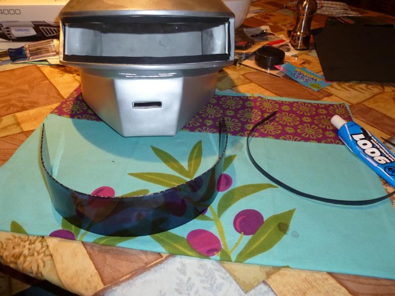
Then I used craft foam to fill in the unpainted areas so as to make the visor seamless to the outside viewer.


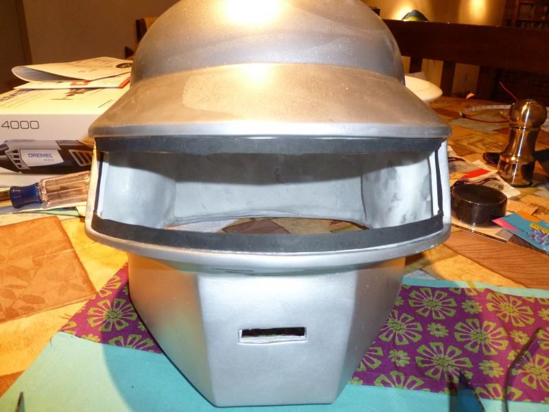
Once this was done, installing the visor was a pain in the rear. I used E9001 glue to hold it in place. Works great once its dry, but I had to hold it in place for an hour to get it to stay in place.


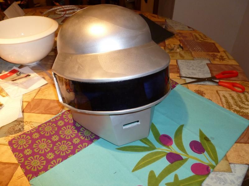
2. Create inner visor

This is what the PETG looks like without the blue covering. This is after I dropped it into boiling water and used the helmet to make it conform to the proper shape.


Once I chopped it to the proper size, I used a sharpee to mark the actual visor size for the inside mounting of this piece. It also guided me in choosing the right length to cut the LED strips to. Just like in Tron Legacy, I am going for 4 rows.


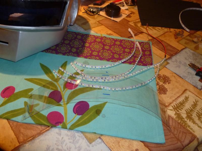
Then I attached the strips as even as I could, with a slight gap between them for viability. As in my other helmet project, when put up to your face, you can see through this fine.


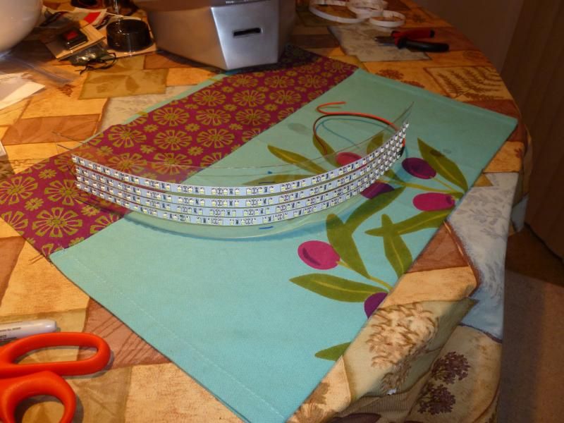
Thats as far as I got tonight. I'll have this done tomorrow at the rate things are going.
 
Looking good, the visor looks to have come out very well. Is that the final positioning for the LEDs? From that angle they don't look evenly spaced.
 
Looking good, the visor looks to have come out very well. Is that the final positioning for the LEDs? From that angle they don't look evenly spaced.

I saw it too, and repositioned that bottom row since this last picture. New pictures tonight will show its much more consistent. The LED strips have enough tolerance to them to be not a perfect line of LEDs, but you'll find the light effect very satisfying trust me.
 
Final updates for this project. Took way longer than I thought, but the results look pretty good.

Continuing with visor creation.....

Forgot I had these, little breadboard jumpers from Radio Shack that happened to be the perfect size for the next task: making the voltage common between the strips, without shorting power to ground.


My soldering setup (this makes me want to buy an actual table in the future, pardon the mess)


And the resulting solder job:


And it worked! This picture is funny, they are so bright at that angle it just looks like a solid light panel to the camera.


Measured the current draw on 12V: a whopping 840mA continuous. Not shocking to me, I expected it, but its pushing the current capacity of the 22AWG speaker wire I'm going to use (max is 920mA)


A better picture of the lights.


And a perspective shot from inside the visor. It proves that you can see through at least when its off. I don't anticipate being able to see at all when the lights are on; too much splashback reflection from the front visor due to the inevitable gap between them. Its not really a problem, its just a feature you have to live with. Having a handler helps...


Quick test fit inside the helmet....looks authentic to me :cool


A closer view shows the slight imperfections. In practice nobody but me and the client will notice. It still lines up well enough to get the job done, and done well.


Drilled some holes for mounting of the visor. Idea was, like the last helmet I worked on, make the visor removable if its necessary.


3. Install inner visor

This process took patience and time. The battery I chose for this, a 6800mAh lithium ion 12V, is heavy enough to apply pressure to the screws to glue it nicely.


4. Prepare battery box

Skipped a few steps before this picture, but basically a dremel and a drill got me this far. I used a strap system I have had much success with in the past, and hot glue to secure it.


Dremel does ok, but the results typically aren't perfect. Need two holes because of the design of this battery. One is needed for the cable to come out, and one is needed large enough to get a finger in there to flip its switch on and off. Subsequent pictures will show the idea.


Installed some panel mount components. A toggle switch and the main power connector (a size M) to interface to the battery.


Anticipating a hefty total current load (840mA for lights, and 80mA total for fans > 920mA), I used thicker wire (16AWG) to connect to the switch, which can handle like 2A. Then the speaker wire 22AWG connectors distribute the current appropriately.


Using EL wire connectors for the two power outputs (lights, and fans). I like these because they are cheap, robust, easy to use, and force a polarity that if wired correctly (my job), the client can't screw it up connecting them backwards.


Final wiring of the box. The switch holds of the (+) end of the battery and the (-) is distributed to both outputs. I potted all connections after test with hot glue, to give it structural toughness, protect against shorts, and just makes it more reliable.


And here is the battery in the box. Some careful maneuvering gets it in there, with some foam to space it nicely, without too much trouble. To charge the battery, the client will have to open the box to access a charge port, tucked into the side in this picture.


Box all sealed up, tested, and ready to go.


And here is the finger port for the power switch of the battery. Theres a small red LED in there that is visible through these gaps.


5. Wire up helmet

Wiring of the lights came out at just the right length. Positioning of the fans, and the wires, took a little more work. Here is after I mounted the fans (pointing up) using hot glue.


Making the fans symmetrical required wiring on longer than the other. Here I attached an extension to bring it over to the other side of the helmet. By the way, soldering to stuff with the helmet attached is not fun at all.


After much pain and suffering, and more hot glue, the final wiring of the helmet is shown below. I made it so that cables have to connect to the helmet at the skull base, which then go to the battery box. In the past my helmets have forced only one disconnect, at the box, and I hated it. Having 2 disconnects complicates things slightly, but gives great flexibility if you want out of that helmet at any time.


Here are the cables attached to the helmet and battery box for the final assembly.


And the final product


I tested it, and sure enough, I can't see anything when the lights are on. The client will need to have a handler, or do the whole "lights on for pictures and standing around, lights off for walking" thing.

This was a straightforward project, but fairly time consuming (in terms of planning, actual execution took 2 evening sessions). I believe my client will be pleased with the results.

Thanks for checking out my thread.
 
Last edited:
Back
Top