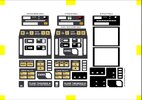
TR-595E Custom Tricorder

build plate.jpg


Today I'm starting on build #2. With this build I'm going to make some improvements to the tricorder including better decals, better hinge attachment, better animations on the LCD and correcting the glaring omission to the previous model- sound. Any changes made to this version will of course be made available via the github repo. I'm going to try to do a better job of documenting the process here as a reference to anyone building the tricorder.

So, let's get started!

Fresh off the printer and with supports removed, we have the Main Body, Door and Lower Interface panel

printed parts.jpg


I like to give the parts a light coat of primer before I start filling and sanding- it helps highlight layer lines and imperfections that will need to be fixed.

primer 1.jpg


primer 2.jpg


These are drying as I type this, so when that's done we'll start sanding and applying filler.
 
Last edited:
View attachment 1637327

Today I'm starting on build #2. With this build I'm going to make some improvements to the tricorder including better decals, better hinge attachment, better animations on the LCD and correcting the glaring omission to the previous model- sound. Any changes made to this version will of course be made available via the github repo. I'm going to try to do a better job of documenting the process here as a reference to anyone building the tricorder.

So, let's get started!

Fresh off the printer and with supports removed, we have the Main Body, Door and Lower Interface panel

View attachment 1637328

I like to give the parts a light coat of primer before I start filling and sanding- it helps highlight layer lines and imperfections that will need to be fixed.


View attachment 1637332

These are drying as I type this, so when that's done we'll start sanding and applying filler.
Beautiful putty, sanding and primer! Clean and smooth. Great start! Definitely following
 
After the primer dried, I used a sanding sponge to sand down the layer lines and any bits of stringing and supports that I missed. Next comes filling:

bondo.jpg


I used a fairly generous amount of Bondo Glazing and Spot putty to coat the surface of the tricorder. I didn't bother with the control surfaces as they'll be covered with decals later on. Be careful not to get too much putty in these areas or the hinge slots as you'll have to chisel it out later. Make sure you give this a few hours before sanding. I'm going to leave this one overnight.

putty front.jpg


putty bottom.jpg
 
Once the putty was dry, I used a sanding sponge to sand the excess off down to the plastic.

putty sanded.jpg


I use Green Stuff putty to fill in the gap and shape the corners of the forward array. I like using Green Stuff here because of how well it holds its shape and how sandable it is. With some sanding and primer it's very easy to get it to blend in with the rest of the model.

greenstuff 1.jpg

greenstuff 2.jpg
 
You custom designed Tricorder looks great! This could have easily been a canon Tricorder successor or a better version of the DS9 "blood oath" Tricorder. Thank you for the insights into your building process.

I have a few questions about the electronics:
  • Do you use a LiPo battery and if so what size and mAh?
  • Did you make a test run to see how long it can be powered after a full charge cycle?
  • How long does the wireless charging take?
  • Does the Qi charging circuit include charging power management (like overload protection) or do you use a separate LiPo charging PCB and/or converter like a PowerBoost module?
  • Did you guide wires through the hinges or did you just solder power lines directly at the hinges (one side positive and the other negative)?
 
Last edited:
You custom designed Tricorder looks great! This could have easily been a canon Tricorder successor or a better version of the DS9 "blood oath" Tricorder. Thank you for the insights into your building process.

I have a few questions about the electronics:
  • Do you use a LiPo battery and if so what size and mAh?
  • Did you make a test run to see how long it can be powered after a full charge cycle?
  • How long does the wireless charging take?
  • Does the Qi charging circuit include charging power management (like overload protection) or do you use a separate LiPo charging PCB and/or converter like a PowerBoose module?
  • Did you guide wires through the hinges or did you just solder power lines directly at the hinges (one side positive and the other negative)?

Here's the battery that I used. The Qi module didn't include any sort of controller, but I found a premade one on Adafruit:
Lithium Ion Polymer Battery - 3.7v 1200mAh
Adafruit Micro-Lipo Charger for LiPo/LiIon Batt w/MicroUSB Jack

I never did full burn to see how long the battery lasts, however I will say that I've only had to charge it once since finishing it in April. Granted- I only ever turned it on once in a while.

I soldered the wires directly to the hinges.
 
I printed out the back cover, primered and sanded it. Depending on your printer the cover may not fit quite right- I had to sand it down quite a bit to get it to fit properly. Once you have the cover in place you'll need to drill holes in the body to match the holes in the cover. My method is to use a torch to heat up a sewing needle, then push it through the premade holes in the panel and into the frame:

burn.jpg


Once the pilot holes are made, pop the cover off and once again heat up the needle and widen the holes just a bit. Be sure to sand down the excess melted plastic around the top of the holes so it doesn't interfere with how the cover sits.

Next, while the cover is detached, install the screws (I used these: McMaster-Carr):

screw 1.jpg


Finally, install the cover:

screw 2.jpg
 
I just realized I never ordered a Pi Pico for the project, so I'm waiting for that to come in. Also out of superglue, which I'll need for this as well. In the meantime, starting work on the PCBs

20221113_225410.jpg
 
All right! I should have everything I need to finish the project. While waiting for stuff I finished assembling the PCBs and painted the main body of the tricorder (Duplicolor BGM0347 Medium Gray Metallic). Today I'm assembling the hinges.

hinge 1.jpg


I lightly sanded down the surface of the hinges to help with solder adhesion, then placed a pad of solder down before attaching the wires. Be careful to place your solder pads close to the knuckle of the hinge- the wire holes in the door are somewhat low, so if the solder points are too high on the hinge leaf it won't fit properly. I actually placed these pads too high and didn't realize until it was too late. I had to file down the openings a bit to make them fit.

I used 30ga wire on the door side of the hinges.

hinge 2.jpg


On the other side, I used a very fine wrapping wire that I had lying around. I think it's also 30ga but the coating is much thinner allowing it to be pushed through the hinge slots on the tricorder.

hinge 3.jpg


I think I got lucky here. On the first build the hinges were a miserable ******* to install without ripping off the wire. Worked out ok here though. Moving on...

hinge 4.jpg


Before securing the hinges, make sure you fix the door in place with painter's tape. This will help ensure the door will close properly.

hinge 5.jpg


Superglue the hinges down. On the first build I only used superglue to hold the hinges in place, but here I'm going to add some JB Weld in place to help secure them.
 
JB Weld applied. You don't need much- I only used just enough to fill in the holes and gaps, but that should be plenty to reinforce the hinges.

JB Weld.jpg


Oh, and while you've got the JB Weld out, go ahead and apply some to secure the hinges inside the main body.
 
Last edited:
Uh oh...

I skipped a crucial step and forgot to test continuity across the hinges BEFORE permanently attaching them to the tricorder.

It doesn't work....

I don't think I sanded the hinges down enough- I'm not getting anything on either hinge. It's going to be a serious pain in the ass, but I think I might be able to fix it with the hinges in place. If not I'll have to start from scratch...

giphy.gif


Update: Looks like Hinge A is actually working. It was tight quarters, but I was able to fix the main body side of Hinge B without too much trouble once the JB Weld set. Once it's done curing I'll work on filling/sanding/priming the door hinge panel. In the meantime, I attached the lower interface PCB to the detached panel:

if_panel_1.jpg


I attached the PCB with hot glue. Be careful when applying the glue- you'll want to avoid gluing the sides and center top/bottom as that's where the panel will attach to the door.

if_panel_2.jpg
 
Last edited:
With the JB Weld cured, I filled in the remaining gaps with the Bondo putty, then sanded it down and primered. If you painted the main body previously, be sure to mask it off as well as the IF panel openings before applying primer to the door. The paint and primer likes to scrape off the hinges when they move, so make sure to let it dry completely before moving the hinge.

doorprep1.jpg


I glued the door magnet in place during this step.

doorprep2.jpg
 
Nice! Sorry I forgot to update on this as my temp job has now more or less became permanent.
I have yet to transfer the latest PCB design to Arky (Top Panel, Front Array) after I have corrected a missing wire link.

Speaking about the decals, I have also modified them a little. Because I did not have anyone to 3D print the files, I got them done with JLCPCB. From the image below, the middle design is for that and is slightly bigger. Do ignore the GEO, MET, BIO as I was planning to learn Fusion360 and modify the Lower Interface .stl file. Alas, that did not go to plan.

The third design on the right was for me to try out various printing services where it is to be printed in black as a light mask but actually, it is not necessary. So, please ignore it.
 

Attachments

  • decals Modified V02.jpg
    decals Modified V02.jpg
    144.1 KB · Views: 83
Not a ton of progress in the last week or so. I ended up buying a sound board for the project (Adafruit Audio FX Mini Sound Board - WAV/OGG Trigger - 2MB Flash). It probably could have been done using the pico, but I got lazy, haha.

I used the resin printer to print off the clear rods for the sensor array and the EMRG button. The tolerances are pretty tight, so you'll probably have to sand the rods down a bit.

20221205_061039.jpg


Solder in a couple of leads to the front array PCB, then hot glue the board in place:

20221205_090605.jpg


Paint the EMRG frame black and then glue in the button:

20221205_090534.jpg
 
Does anyone have a decent tricorder warble loop? The closest I've been able to find is this, but messing around with it in Audacity I haven't been able to get it to repeat smoothly.

Edit- Nevermind, haha. I sent the link to a buddy of mine and he had it fixed in about five minutes. Going to start working on the sound board now.
 
Last edited:
Got a bunch done today- Started by wiring up the Pico to the display, then set the display into its frame in the tricorder.

20221206_202738.jpg

20221206_202927.jpg


Wired up the reed switch, then glued it into place:

20221206_204309.jpg

20221206_204531.jpg


Here's the audio circuit assembled. Interesting note, the speaker I'm using here actually came from one of the old Playmates TNG tricorders!

20221206_205627.jpg


More assembly:

20221206_211036.jpg


Once everything is in place, connect all of the positive leads, then connect all of the ground leads

20221206_222709.jpg


I forgot to take pictures before I closed up the unit, but the battery and charging circuit get tucked in there too. The Qi module is attached to the inside of the door panel.


Next up, decals!
 

Your message may be considered spam for the following reasons:

If you wish to reply despite these issues, check the box below before replying.
Be aware that malicious compliance may result in more severe penalties.
Back
Top