Tom’s ROTJ Vader MOM saber!

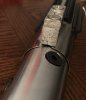
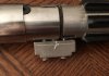
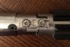
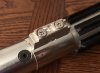
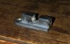
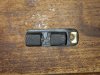
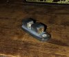
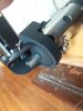
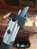
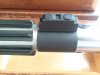
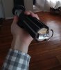
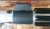
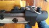
that ******* box could be anything... dying for someone to do a CNC run of aluminum parts for this saber... the DV6 is my fav vader saber..

tom your doing a excellent job

I found the master for my control box in storage the other day and making a mold of it now. Casting myself a few in pewter, but I hope someone does an aluminum run as well. Would love to replace a cast piece with a cnc machined part :D
 
So PropReplicator made my dreams come true. Well, one of them - for 25 USD shipped to me in NY he was able to cast this in pewter. Now, my drill press got hot enough to fuse the pewter to the bit, so I had to gouge the steel bit out of the box. Caused some damage, but I’ll putty it up!

now, I drilled and tapped two countersunk screws (recently bought 12 lbs of screws in a drawer organizer for my shop from an estate sale...) anyways, I screwed up the first hole on the saber body and realigned them correctly, covering the first hole with the activation box. Now two screws are tapped through the box, graflex and into the metal
core

i drileld the hole on the lower graflex body a little higher, meaning it is spaced a little further away, and stuck in place with some gaffer tape and an extra hidden screw. (Guess three screws keep things from wobbling not two, hence the gaffer tape)

anyway, the clamp band is just some sink pipe sliced up, and pinched under the box - gonna smear some glue underneath after I paint it up.

i also noticed those MOM pics of the saber reveal how it stayed on that pinth - there’s a dab of hot glue between the clamp band and the plexi cradle, with some strings stuck to other parts of the saber!
 

Attachments

  • E8B09EE0-22BF-4549-8F9F-B22498076146.jpeg
    E8B09EE0-22BF-4549-8F9F-B22498076146.jpeg
    1 MB · Views: 226
  • 1EDE5678-A35E-421F-8A1F-A1EA7B8D1CBF.jpeg
    1EDE5678-A35E-421F-8A1F-A1EA7B8D1CBF.jpeg
    1.6 MB · Views: 218
  • CB3BE1A6-B2F9-4B3F-BEE4-056177B4AD5D.jpeg
    CB3BE1A6-B2F9-4B3F-BEE4-056177B4AD5D.jpeg
    1.3 MB · Views: 237
  • 23F2246D-C2F9-4485-9291-7143E9E7F574.jpeg
    23F2246D-C2F9-4485-9291-7143E9E7F574.jpeg
    1.1 MB · Views: 221
  • 39BCB031-DE16-4031-A43C-387FACD0F244.jpeg
    39BCB031-DE16-4031-A43C-387FACD0F244.jpeg
    1.1 MB · Views: 228
  • 3E8E1A6C-528F-4BD7-8B89-95C4AEC5355A.jpeg
    3E8E1A6C-528F-4BD7-8B89-95C4AEC5355A.jpeg
    602 KB · Views: 232
  • 58DF8B18-0264-41A3-BC93-318CF19D1A78.jpeg
    58DF8B18-0264-41A3-BC93-318CF19D1A78.jpeg
    900.8 KB · Views: 219
  • 7873CD2C-4706-4D1F-B59F-1FE7DFB21B1C.jpeg
    7873CD2C-4706-4D1F-B59F-1FE7DFB21B1C.jpeg
    664.6 KB · Views: 211
I nearly forgot ...I took the brass current ball catches and sculpted some apoxie sculpt over it, replicating the shape of the non existent stamped versions!
 

Attachments

  • A5F40CDB-5B48-4E7E-B9B2-EF74EBF7EEB1.jpeg
    A5F40CDB-5B48-4E7E-B9B2-EF74EBF7EEB1.jpeg
    505.9 KB · Views: 221
  • 00AD34B6-D375-48D8-9C22-86FB5F87CAE5.jpeg
    00AD34B6-D375-48D8-9C22-86FB5F87CAE5.jpeg
    920.7 KB · Views: 216
  • FD7063BF-13A1-4B91-B2B1-D8F2D4948A3A.jpeg
    FD7063BF-13A1-4B91-B2B1-D8F2D4948A3A.jpeg
    573.6 KB · Views: 207
Very cool, Tom. I did a first draft of one of these for myself earlier this year, so it's exciting to see your take on it. (My hex screws all have lettering on the heads. Where did you find your blank ones, if you don't mind?)

I'm surprised you're using the top section of the Graflex's innards in your build. Looking at some of the MOM reference photos folks have shared, it looks to me like this one shows the full ring of the Graflex tube without a lip sticking out to interrupt it:

DVROTJ08.jpg

This one makes me thing the rectangular hole is filled, and that the circular hole doesn't continue up under the shroud:

dv_ls_rotj_02.jpg

And in this one I don't think the black plug looks high enough to be on top of the top part of the innards, because it doesn't cover up enough of the far side of the S-curve:

dv_ls_rotj_01.jpg

It could be I'm misreading these, or you've seen something in the other photos I've missed. I'm curious to know what you think. Thanks!
 
Hey, Tom, since you're working on one of these, do you think that the V3 clamp holes would line up at all with the bottom hex screws on the Graflex upper, like so? It's been something that's always bugged me to know.

V3MoMRef.jpg
 
Hey, Tom, since you're working on one of these, do you think that the V3 clamp holes would line up at all with the bottom hex screws on the Graflex upper, like so? It's been something that's always bugged me to know.

Here's how my Spirit of Obi1 V3 clamp aligns with a print of the template:

_DSC1948.JPG

I could get the holes second and third from the left to line up with the nearest screw marks on the template, but the holes would still be too small for the allen-head bolts to get anywhere near flush, and the other two holes would be even further out of alignment.

Drew
 
Here's how my Spirit of Obi1 V3 clamp aligns with a print of the template:

View attachment 838378

I could get the holes second and third from the left to line up with the nearest screw marks on the template, but the holes would still be too small for the allen-head bolts to get anywhere near flush, and the other two holes would be even further out of alignment.

Drew
whoa - they do seem really close though, interesting. I'm pretty sure the R2D2 casting showed a little countersinking to the holes, though they most likely covered the clamp in Gaffer tape to save mark's hands.

As for the emitter on this saber - good catch! I used the top mainly because just the center of the socket seemed such a hassle and thats not something the prop guys bothered with a lot. I was assuming as a ESB stunt the whole side socket was visible so they'd have to use both the upper and middle sections of the socket. Now I'm looking at it though - you're right that the socket's rim seems to be not there!


Also the V3 clamp is upside down, the long slot is near the pommel cubes
 
Oh! and the bolts I got at an antique shop a town away, They had a hardware section and the owners actually separated screws, knobs, parts, you name it, into little baggies and priced them. there was a drawer of these counterunk black allen bolts and I just bought them without measuring, they did happen to be the right size though! I think they're 1/4 20
 
I noticed in the picture you posted on facebook that your controlbox is positioned backwards, also visible in your pics in post #62. Check your reference or post #66 by Drew and you'll see the opening of the controlbox is towards the front/emitter/screws, not the back with the T-tracks :)

Chaïm
 
Oh! and the bolts I got at an antique shop a town away

I guess a modern supplier was too much to hope for! Oh well.

(And thanks for the reminder about the V3 clamp -- I put it on the wrong way round when I reassembled it after the photos, despite knowing it was supposed to be upside down.)
 
So, after some help from a few members I got some metal parts. Had to grind out the shroud for the vintage graflex (pulled shoulders, screws and stuff) and I puttied and sculpted over some of the screws poking out of the box. High heat grill paint is what I used to paint, and the puttied ball catch is on with VHB tape for now, until I get another one. The gaffer tape and two screws seem to hold the bottom on I guess!

So, watcha think? This is the first solid core ROTJ Vader saber that I know of, especially after seeing that BTS video

- - - Updated - - -

Dammit the clamp box is backwards, I do this every time. Meh, it's a small detail!
 

Attachments

  • 20180830_121712.jpg
    20180830_121712.jpg
    486.5 KB · Views: 238
  • 20180830_121734.jpg
    20180830_121734.jpg
    563.3 KB · Views: 244
  • 20180830_121750.jpg
    20180830_121750.jpg
    1.4 MB · Views: 232
  • 20180830_121830.jpg
    20180830_121830.jpg
    532.7 KB · Views: 234
  • 20180830_122321.jpg
    20180830_122321.jpg
    1.2 MB · Views: 231
  • 20180830_122358.jpg
    20180830_122358.jpg
    1.7 MB · Views: 226
  • 20180830_122441.jpg
    20180830_122441.jpg
    1.1 MB · Views: 231
  • 20180830_122522.jpg
    20180830_122522.jpg
    2.2 MB · Views: 220
  • 20180830_122606.jpg
    20180830_122606.jpg
    1.2 MB · Views: 226
I'm surprised you're using the top section of the Graflex's innards in your build. Looking at some of the MOM reference photos folks have shared, it looks to me like this one shows the full ring of the Graflex tube without a lip sticking out to interrupt it:

View attachment 838325

This one makes me thing the rectangular hole is filled, and that the circular hole doesn't continue up under the shroud:

View attachment 838326

And in this one I don't think the black plug looks high enough to be on top of the top part of the innards, because it doesn't cover up enough of the far side of the S-curve:

View attachment 838327

It could be I'm misreading these, or you've seen something in the other photos I've missed. I'm curious to know what you think. Thanks!

I actually had to dremel off the lip on the plastic socket.
 
Toms quiet... this could be a good thing, he’s working on projects ;)

All joking aside tom, I’ve been in and out. Have you and everyone else talked about the possibility of the bottom tube being a cut down 5 cell?

Is there any theory’s on what exactly they used? Like the salt shaker?


Sent from my iPhone using Tapatalk

haha I AM working. This one is mostly done unless I can find a good ball catch. I decided to not clear coat the black paint, seems pretty durable. I am worried because the shroud is ground out so I can see light between the shroud and graflex. The red button socket and the front socket area are hammered into place though, so it shouldn't come off...

I'll post about some of the other projects I have soon ;)

the bottom... I'm convinced it is a slightly sanded nickel plating finish, probably to get the glue off the ESB grips. Thing is... the holes are backwards, like the tube was drilled upside down by accident. So, I don't think it's a 5 cell based on it's previous use.
 

Your message may be considered spam for the following reasons:

If you wish to reply despite these issues, check the box below before replying.
Be aware that malicious compliance may result in more severe penalties.
Back
Top