Studio Scale B-Wing Starfighter Build Thread

thibkaji

Well-Known Member
It's been a few months, but I've not been idle! I'm back now with a new studio scale build thread for the B-Wing Attack Starfighter! This ship is one of my all-time favorites -- everything about it I find cool and awesome, and so I've decided to have a go at it. I might be out of my mind -- in fact, I KNOW I'm out of my mind -- for attempting this build when I've only created one other SS build prior. But to quote the Cheshire Cat, "We're all Mad here..."

Leading up to now I've done a TON of research, combing through other threads here on the RPF and other sources, but mostly my own independent research using reference photos and scouring through kits and scans to identify as many kit parts as possible. I've also had some assistance filling in a few really hard-to-ID kit parts from a few folks who, upon request, have chosen to remain anonymous. The result is that I've got a pretty complete picture of everything needed --at least kit-wise -- and I'm going to be detailing the build here.

So let's jump in and get going!

First, an obligatory picture of kits collected thus far. I have another 4-5 kits still on the way, and that should put me into pretty good shape. It's a lot of kits compared to the bomber, with some contributing only 1-2 parts. I think I'm at around 28 total unique kits thus far, but I'm still researching a handful of unidentified parts, so that could go up.
Kit_List.jpg


And, yes, that F-14A box is REALLY rough (it's what's inside that counts!)!

I'm planning to build this as much like Bill George did at ILM as I possibly can, and this of course means vacuum-forming multiple parts -- the cockpit halves, the main wing halves, the engine housing halves, the upper neck, the main wing gun surround and probably the wing gun housings. I'm in the process of building my own vacuum-forming machine, and will be working up the bucks needed to cast the parts.

As another preparatory step, I also picked up the Bandai 1/72 B-Wing kit. This kit was created using scans of the original filming model, and I can tell you it's super accurate!! I'm amazed at how they were able to reproduce, at scale, a number of obscure parts on the kit. Just amazing, and an excellent resource for making measurements -- this will be especially useful when I go to make the bucks. My only real complaint with the model is that the scale isn't actually 1/72 -- it's much closer to being 1/80th scale. I determined this through numerous measurements of the actual kits parts vs. the representation of the parts on the Bandai kit. This means that for any of the measurements I might need I have to end of multiplying it by around 2.54x on average.

And with that, let's begin!


The Cockpit Neck Mid-Section

I wanted to get going on this build, so I picked a section I thought would be easy enough to build -- so I went with what I'm calling the "cockpit neck". This section is made up of two Airfix Saturn V rocket parts, some Leopold parts and styrene strips. I know there's been some debate as to whether it's an Airfix, Revell or Entex kit that contributes to this, but as you'll see, all of the reference markings definitively show it's the Airfix kit.

First thing was to trim up the halves -- you can see the trimmed up section on the left and untrimmed on the right. This primarily consisted of removing the thin locking section at the front and sanding down all of the raised sections around the perimeter (with the exception of the large bump still on the left-hand half).
Middle_Cockpit_01.jpg


Then I glued up the halves together. There is a collar that goes around where the cockpit connects to this section and so I also cut out a disk of styrene and glued that to the end to act as the main support for the collar.
Middle_Cockpit_02.jpg


This was followed by the collar itself.
Middle_Cockpit_03.jpg


Finally, I added a few strips of styrene around the perimeter to match the reference.
Middle_Cockpit_04.jpg


Once I got to this point, something about it kept bothering me. Looking closer, I really didn't like the raised sections around the perimeter of the Saturn V parts. This was creating an uneven shape, and looking again at the reference pics, I wasn't finding any indications that these sections were on the filming model. They needed to go! Unfortunately, while attempting to fix this I ended up screwing it up. Luckily I had another Saturn V kit ready to donate!
Middle_Cockpit_04a.jpg


Here you can see the two halves with the raised sections cut off -- not really a circle anymore, is it?
Middle_Cockpit_07.jpg


With a little friendly coercion I was able to glue it up and into a circular shape. The disk inside the assembly is part of the coercion, keeping the shape from pulling back into an oval.
Middle_Cockpit_08.jpg


I added all of the strip styrene back -- this looks a LOT better! You can see now where the cut marks and protrusion I left in place match up to the reference.
Middle_Cockpit_10.jpg

Middle_Cockpit_05.jpg


Throw on a few Leopold parts and the last of the needed styrene and this section is looking pretty good.
Middle_Cockpit_11.jpg


The reference also shows a few of these little triangular shapes, which are the result of sanding off the raised sections around the Saturn V parts. With this current version, these markings also now line up.
Middle_Cockpit_11a.jpg

Middle_Cockpit_06.jpg


I still need to add a bit of wiring, but I think it's a pretty good start for this build. Once I've worked out the armature, this will have to get mounted to that, likely with a hole cut through the bottom and a bearing to allow for cockpit rotation. I'll also have to run electrical wiring down through the neck so I can light up the rice lights in the cockpit.


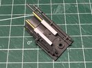
Next up I will be tackling the cockpit itself. Here's a teaser with the kit parts I've collected so far:
Cockpit_Prep_01.jpg


And with that we're off! I'm expecting this to be a fairly slow-burn of a build. I have lots more research still to do -- need to work out the structure of the armature, finish building the vacuum former, and create all the bucks needed -- not to mention finish gathering kits, parts, and working out the rest of the assemblies. But I've got a lot figured out already, and look forward to sharing my progress with everyone. Til next time, keep on scratchin!
 

Attachments

  • Middle_Cockpit_09.jpg
    Middle_Cockpit_09.jpg
    1.2 MB · Views: 78
Last edited:
What?! Another update? Thought this was a slow-burn thread? Welp, I’m sitting idle at the airport watching my flight get delayed and figured I’d post something, as I’ve gotten a bit further ahead than posts may indicate.


Cockpit Interior

First step was to figure out what the base pattern is for the interior of the cockpit that all kit parts attach to. I did a number of measurements and ended up with a shape 1mm on each side smaller than the cockpit shell size. I cut that initial base out of .040 thick stock.
IMG_1721.jpeg


Next I started adding some kit parts to make sure my spacing looked right. I also noted that on the reference there appears to be another thinner layer underneath this one, so I added that layer. I also padded up the back sides, as the Bismarck/Tirpitz parts that go there should be elevated a little. Parts are looking pretty good so far.
IMG_1727.jpeg


Once I was satisfied with the general shape/size, I began work on the rear of the cockpit. For this I cut a circle out of .040” thick stock and figured out using the ref images about how far down from the top the kit parts begin. I also cut up the F-14 parts that flank the rear seat. I also worked up a more structured cockpit shape and attached the rear to the rest.
IMG_1740.jpeg

IMG_1742.jpeg


I wasn’t happy with how the top surface looked — I didn’t think it was accurate enough so I redid it a bit. I’m much happier with v2:

IMG_1745.jpeg

IMG_1748.jpeg

IMG_1747.jpeg


So now what’s a cockpit without a pilot? The head for the pilot is off ground crew in the F-14, but the body of the pilot. So I went to town hacking the head off and reattaching it to the other body.
IMG_1728.jpeg

IMG_1731.jpeg


I also hacked off his feet, as they are missing in the studio model.
IMG_1741.jpeg


In addition, I also chose to work a bit on the under-cockpit gun assembly. The base is from the Mörser Karl, cut down as shown, with a gun from the same kit on the left side and an Sd.Ah.52 gun in the right. 3mm tubing with brass tube inserts completed the base look.
IMG_1724.jpeg

IMG_1726.jpeg

IMG_1725.jpeg


More parts are needed, but I’m waiting until I have the cockpit shells before I do those.

With that I went about attaching all the kit parts I had to the cockpit base. Add a pilot, and it’s looking pretty snazzy!
IMG_1805.jpeg

IMG_1806.jpeg

IMG_1807.jpeg


I’m still missing 3-4 parts that need to go into the cockpit, and those should be in my hands by the time I get back from traveling — I’ll update once the cockpit is truly done.

I also attached the chin gun. Why not? I’m sure I’ll have to move it so it’s barely attached, but I couldn’t resist!
IMG_1756.jpeg

IMG_1755.jpeg


And that’s where we are! And just in time, my flight is now ready to board. I have a few other in-progress pics for smaller sections I’ve been working up, and I might post those while traveling. Else, I’ll post once I’m back and can get more work done. Til next time!
 

Attachments

  • IMG_1722.jpeg
    IMG_1722.jpeg
    1.6 MB · Views: 75
Last edited:
I’m back! With a pretty small, but for me, important update. A few more kits have arrived at Casa de Scott, not least of which was the 1/350 Tamiya Tirpitz, which is a must-have for this build. The Tirpitz and the Bismarck share a lot of parts, and a lot of the cockpit can be built with either one. However, the “dash” section for the B-Wing comes exclusively from the Tirpitz, so if you’re following along, you’ll need one of those, too. It’s also needed for a few more parts, and this update is mostly me fitting those parts in.

So let’s continue with the cockpit!

First, I added these two parts from the Tirpitz along the inside sides of the cockpit. These walls were layered styrene, so I had to cut away the outer most layer to properly fit in these parts.
IMG_1869.jpeg
IMG_1868.jpeg


Looks a ton better, a much more finished look!

Here are the two parts needed for the main dash section I alluded to earlier.
IMG_1870.jpeg


The bottom one get glued behind the top one. Sorry, I didn’t take a lot of in-progress pics at this point as I was super excited to get this installed. And here it is, all fit in.
IMG_1872.jpeg


Lastly, I installed the control handles from the F-14 to pretty much finish off the kit portion of the main cockpit area. I gotta source some rice lights and get the wiring installed for this, but until the shells are made, this is about where I’m gonna leave this.

Some more pics, cause why not?!

IMG_1874.jpeg

IMG_1875.jpeg

IMG_1876.jpeg


This feels like a bit of a let-down, so I’ll throw one more thing I’ve been working on in here — the engine vent assemblies.

There are two of these vents on the B-Wing, meaning you’ll need two 1/12 Tamiya 312T4 kits to make these, plus a pair of parts from the PT-15, a pair from the 1/20 Ligier, and a pair from the 1/24 Airfix Harrier.

First, take those lovely 312T4 engine blocks — and hack them apart! Gotta trim the sides and a bit off the end.
IMG_1765.jpeg

IMG_1766.jpeg


Next, glue the Harrier missile rack part to the bottom and the PT-15 part to the end to cover up the hole. You’ll also need a piece of styrene to go under the PT-15 part, as it’s not tall enough to fill the gap.

IMG_1767.jpeg


This is the Ligier part that then get glued underneath this engine vent assembly.
IMG_1822.jpeg

IMG_1820.jpeg


A few strips of styrene down the one side and voila! Final result is an engine vent sub-assembly!
IMG_1821.jpeg


Now use your duplicator and create another, so you have two.

IMG_1826.jpeg


And that will do it for now! I’m continuing to build my Vac-former, but it got cold out and so it’s miserable working in my garage. I’ll be focusing more on getting that up and running over the next few weeks, with minor updates on sub-assemblies until then. Gotta also start figuring out an armature — I’ve got an idea, but if anyone knows what the original looked like or have any advice, I’m def open to it!

Until next time, keep on scratching!
 
Last edited:
Bbbbrrrrr…! It’s -2 deg F in my garage, so work on my vac-former has ground to a halt. Good news is the heater unit is in and working — just need it to warm up some so I can finish making the platens and holding frames. So what’s a guy to do?

Build the main wing gun assembly, of course!

This assembly has a LOT going on. I’ll try and detail as much as I can. Let’s go!

Main Wing Gun Assembly


I chose to start off with the base of the assembly that everything attaches to — the engine/transmission part from the 312T and the backside of a gun assembly from the Gepard.
IMG_1893.jpeg


To this I attached this M2 Long Tom part and a small square of styrene underneath that part:
IMG_1894.jpeg


Next up was the Leopold gun, which I cut down. I added a small piece of styrene tubing to act as a spacer to keep the gun better aligned when attached and give it more surface area for gluing.
IMG_1899.jpeg


I also attached some Mörser Karl parts, another Long Tom part, and a box from I think the Sd.Ah.52 (I’ll have to verify that!):
IMG_1900.jpeg


I’m not sure if ILM used epoxy or another putty to fill the gap between the Leopold gun and 312T part, but it’s clearly filled in on the ref. Used some Milliput I had lying around to fill the gap on mine.
IMG_1901.jpeg


Attached the ubiquitously used SD.AH.52 gun and this filter unit from the P34 Tyrrell:
IMG_1903.jpeg


And the Long Tom gun:
IMG_1904.jpeg


You’ll notice perhaps that the barrel of the Long Tom has been cut off — on the blue variant of the B-Wing it remains attached but I’m guessing it broke off on the meatball version and (as you’ll see later) was reattached in a different spot.

Next I took on the other large cannon, which is pretty much just the 1/25 SU-100 cannon with a PT-15 part on the back side of the tip and a P34 part on the end. This end has 1/8” dia stock pushed through the end, so I drilled out the end to size before assembling.
IMG_1895.jpeg

IMG_1897.jpeg

IMG_1906.jpeg


It’s looking pretty good! Can add some “cables” to the top
IMG_1909.jpeg


And one side (oh yeah, there’s another P34 canister there, too!). I added some styrene tubing to the end to extend it for better gluing surfaces. I realized after that there’s another hose part like this that has a longer end I could have used, but oh well!
IMG_1912.jpeg


Remember that Long Tom gun I mentioned earlier — handling that here with some tube stock and the tip from an Airfix Harrier.
IMG_1918.jpeg


And attached. It’s such a weird place to put this gun back on…
IMG_1919.jpeg


Last thing I did was attach some Gepard parts to the back side. You can’t see these in the reference pics, but they’re present on the gun assembly from the Bandai kit (attached to an Entex Porsche Transmission part — yeah, not going after that one!), so I added them. I’ll probably have to cut them up when I get to installing this assembly, but it works for now.
IMG_1920.jpeg

IMG_1921.jpeg


And that’s it for now. There’s one more hose that goes on the left side (when looking from the front), but I’ll do that after this is installed in the gun housing down the line.

Here are shots of the final assembly!
IMG_1924.jpeg
IMG_1925.jpeg
IMG_1927.jpeg
IMG_1930.jpeg

IMG_1931.jpeg
IMG_1934.jpeg
IMG_1932.jpeg


And some reference shots for comparison:
IMG_1939.jpeg
IMG_1941.jpeg
IMG_1943.jpeg


This was a super fun assembly!! I’m having a blast with this build so far. I just picked up some aluminum rods and blocks and am going to try my hand at machining and assembling an armature for this thing. I’ve also found some hinges with a wide enough center section to cover the two side wing hinge sections. Lots of work coming up once things warm up.

See you all in the next one!
 
Bbbbrrrrr…! It’s -2 deg F in my garage, so work on my vac-former has ground to a halt. Good news is the heater unit is in and working — just need it to warm up some so I can finish making the platens and holding frames. So what’s a guy to do?

Build the main wing gun assembly, of course!

This assembly has a LOT going on. I’ll try and detail as much as I can. Let’s go!

Main Wing Gun Assembly


I chose to start off with the base of the assembly that everything attaches to — the engine/transmission part from the 312T and the backside of a gun assembly from the Gepard.
View attachment 1898411

To this I attached this M2 Long Tom part and a small square of styrene underneath that part:
View attachment 1898412

Next up was the Leopold gun, which I cut down. I added a small piece of styrene tubing to act as a spacer to keep the gun better aligned when attached and give it more surface area for gluing.
View attachment 1898416

I also attached some Mörser Karl parts, another Long Tom part, and a box from I think the Sd.Ah.52 (I’ll have to verify that!):
View attachment 1898415

I’m not sure if ILM used epoxy or another putty to fill the gap between the Leopold gun and 312T part, but it’s clearly filled in on the ref. Used some Milliput I had lying around to fill the gap on mine.
View attachment 1898417

Attached the ubiquitously used SD.AH.52 gun and this filter unit from the P34 Tyrrell:
View attachment 1898418

And the Long Tom gun:
View attachment 1898419

You’ll notice perhaps that the barrel of the Long Tom has been cut off — on the blue variant of the B-Wing it remains attached but I’m guessing it broke off on the meatball version and (as you’ll see later) was reattached in a different spot.

Next I took on the other large cannon, which is pretty much just the 1/25 SU-100 cannon with a PT-15 part on the back side of the tip and a P34 part on the end. This end has 1/8” dia stock pushed through the end, so I drilled out the end to size before assembling.
View attachment 1898413
View attachment 1898414
View attachment 1898420

It’s looking pretty good! Can add some “cables” to the top
View attachment 1898421

And one side (oh yeah, there’s another P34 canister there, too!). I added some styrene tubing to the end to extend it for better gluing surfaces. I realized after that there’s another hose part like this that has a longer end I could have used, but oh well!
View attachment 1898422

Remember that Long Tom gun I mentioned earlier — handling that here with some tube stock and the tip from an Airfix Harrier.
View attachment 1898423

And attached. It’s such a weird place to put this gun back on…
View attachment 1898424

Last thing I did was attach some Gepard parts to the back side. You can’t see these in the reference pics, but they’re present on the gun assembly from the Bandai kit (attached to an Entex Porsche Transmission part — yeah, not going after that one!), so I added them. I’ll probably have to cut them up when I get to installing this assembly, but it works for now.
View attachment 1898425
View attachment 1898426

And that’s it for now. There’s one more hose that goes on the left side (when looking from the front), but I’ll do that after this is installed in the gun housing down the line.

Here are shots of the final assembly!
View attachment 1898428View attachment 1898429View attachment 1898430View attachment 1898431
View attachment 1898434View attachment 1898435View attachment 1898436

And some reference shots for comparison:
View attachment 1898437View attachment 1898438View attachment 1898439

This was a super fun assembly!! I’m having a blast with this build so far. I just picked up some aluminum rods and blocks and am going to try my hand at machining and assembling an armature for this thing. I’ve also found some hinges with a wide enough center section to cover the two side wing hinge sections. Lots of work coming up once things warm up.

See you all in the next one!
Great post! Love the attention to detail that you're putting into this build.

SB
 
Great post! Love the attention to detail that you're putting into this build.

SB
Thanks! I wanted this to be a fairly comprehensive build guide detailing what goes into one of these models. I had trouble finding anything like this that I could use for my build, so this is my way of giving back to the community that future builders could use to help them build one.
 
Were the wing engines made from the AMTronic air car?
Not quite sure what your asking here as there anren’t any wing engines. The main engines are made up mostly of Tamiya A-10 Thunderbolt engines with some other bits added. I believe the insides of the engines were aluminum bells, some styrene around them, and some Hasegawa 1/32 F-16 missile clips for around the outside edge of the engines.

If you’re asking about something else, let me know and I’ll do my best to answer.
 
This past weekend I spent some time working on the B-Wing “pod” section that’s aft of the cockpit. I’m sure ILM used some off-the-shelf components for some of the internals here, but I’m just gonna scratch most of it together.

Started with constructing the v-belt-looking disc that sits right up inside the primary ring. This one right here:
IMG_1964.jpeg


I took some measurements off the Bandai B-wing and other references to land at around 2.2 - 2.3” or so. I cut the two outer rings from .060” sheet stock, and the center from .040”.
IMG_1947.jpeg

IMG_1948.jpeg


With that done, I started heading back toward the rear pod. I found that one of the round kit parts in the Airfix Harrier was a good match for the diameter underneath the Leopard tracks, so I used that as a base and added styrene to form the general shape I wanted.
IMG_1949.jpeg

IMG_1950.jpeg


I then attached that to the v-ring:
IMG_1952.jpeg


And Added treads around the perimeter:
IMG_1953.jpeg


The ends of these treads are slightly covered over by the end ring. Built that up with more styrene strips until I was happy with the look:
IMG_1955.jpeg


I next built up the ring at the end of this section, which is what will attach to the pod section.
IMG_1956.jpeg


Speaking of the pod, there is some debate over what kit part was actually the donor — everyone agrees it’s a space shuttle external tank nose section, but is it Revell, Airfix, Entex?

I had the fortune of picking up an Airfix Space Shuttle kit for pretty cheap recently. I grabbed the nose section and compared the diameter of the nose to what I measured on the Bandai/references and it’s a dead-on match. The shape is right, too, and it’s what I’m using here.

After assembling the cone I cut off the end on an angle that matched the references. I also cut off the bottom 1/2”-5/8” or so to shorten the pod to about 1mm short of the proper length.
IMG_1959.jpeg


The bottom of the pod section has an approx 1mm plate attached to it, and this is what connects to the tread section. To reinforce the disc, I added a thicker .060” thick disk that will fit snugly inside the end of the pod.
IMG_1957.jpeg


Here it is inserted into the end but not attached. I won’t permanently attach the pod to the base until I’ve finished everything else on the assembly.
IMG_1958.jpeg

IMG_1960.jpeg


Last thing for this section is to add panel grooves around the nose, as well as glue in the F-14 engine disc at the end. Getting this installed straight was certainly harder than it seemed!
IMG_1963.jpeg


In the interest of full disclosure, after dry-assembling these different sections I found that the tread section was too large in diameter as built, so I ripped it all apart and rebuilt it about 1/8” smaller, which seemed to be just right. Much happier with the size now, but unfortunately I don’t have any pics of that rebuild.

Here’s a rough assembly of these parts around a thin rod, which I used to keep the assemblies aligned.
IMG_1961.jpeg


Next steps for this are getting a 1/2” dia rod to use as the central rotating shaft, drilling out 1/2” holes through all the sections, attaching all the assemblies to the shaft, and sealing up the rear pod. I’m planning to use a small bearing rod end, which will fit inside the Saturn V section, as the center support for the rotating shaft, and that will thread into the rest of the armature. I don’t have the 1/2” Rod yet, but will soon, and I’ll update how this assembly looks once I’ve installed it.

Til next time!
 
Quick update. Got the 1/2” rod in, so worked to get that installed so I could rotate the cockpit and rear pod assembly.

I added a nylon insert through the front of the main housing to ensure the rod passing through would rotate freely and not wear down the styrene. I also added a small piece of styrene to act as a stop on the rotation. I’m planning to add wiring/lighting through here to the cockpit and don’t want the wires to wrap around the shaft and potentially pull out, so a rotation limit should help to prevent that.
IMG_1970.jpeg


Here’s the tie rod bearing I’m using for the center rotation mount to the armature. It’s a swivel bearing, so it can not just spin but also rotate forward and back. I didn’t want that, so I created a housing around it to pin the rotation in place.
IMG_1971.jpeg


Here’s the 1/2” rod inserted into the rear tread assembly. There’s another nylon bushing in there to keep it well centered before I secured it in place.
IMG_1973.jpeg


Cap I built up on the back for the rod to mount to. It’ll be hidden inside the rear pod so I don’t care what it looks like! LOL!
IMG_1974.jpeg


I also added a small collar to the back of the cockpit assembly, but didn’t take a pic of that. It’s strictly for mounting purposes, to more securely connect the cockpit to the shaft.


And here it is all dry-assembled. Can’t finalize this until the wiring is done, so likely this will not be completed until near end of the build. I’m probably going to add another styrene plate to the back opening of the Saturn V section to both assist in keeping the tie rod in alignment, but properly spacing out the tread section to ensure proper rotation.
IMG_1976.jpeg

IMG_1977.jpeg

IMG_1979.jpeg

IMG_1980.jpeg


Made a short vid clip, too.


And that’s it for now! This weekend I’ll try and get more work done on the vac-former, as well as the armature.

Til next time!
 
Back
Top