Slothfurnace's ANH Luke Graflex Saber chassis. PICS, Step by step.

Excellent!!
Are you a Jedi Master?


I am trying!

Well, tonight I thought I'd tackle the speaker chamber, and found some Delrin to make the speaker retainer rings out of. Normally I would have plenty of pics of the "making of," but my camera battery was dying so I only have a few of the "after making"
045.jpg

You see here the temp speaker, and a speaker grille I found out of an old radar detector.
046.jpg

The delrin rings kind of sandwich the speaker and the grille together, and the outer shell of aluminum holds everything snug. I'll eventually put a set screw in the rear ring to keep it all tight.
047.jpg

The smaller diameter lip of the aluminum cap also secures my battery pack inside the battery can.
048.jpg

I might need to shave a little off for length though, I need to make up about a quarter of an inch someplace so it all fits in when collapsed.
 
Awesome, love it ! Keep up the updates! Super...... saber !!! :cool

Thanks!


A minor update with a quick sketch!
049.jpg

This is how I hope it turns out, a quick sketch to see if I like it before I head towards the finish line...
050.jpg

Last night, I decided to work on my switch, the obvious place to put it is in the red button, but how? The switch the graflex shop sent that "supposedly" fits under the red button is way too thick to fit there... what to do?
051.jpg

Ah, I see the mailman has brought me my Pololu latching switch pcb. hello TINY!
052.jpg

After a bit of modification to the original button, it fits great, works great, and I am very pleased with the tactile feel of the snap of the switch under the red button.
I did have to VERY CAREFULLY remove the little dome tab under the red button for the Polulu to fit, but once I did, everything fits like it is supposed to.
 
Last edited:
This is Great!!

Thanks!

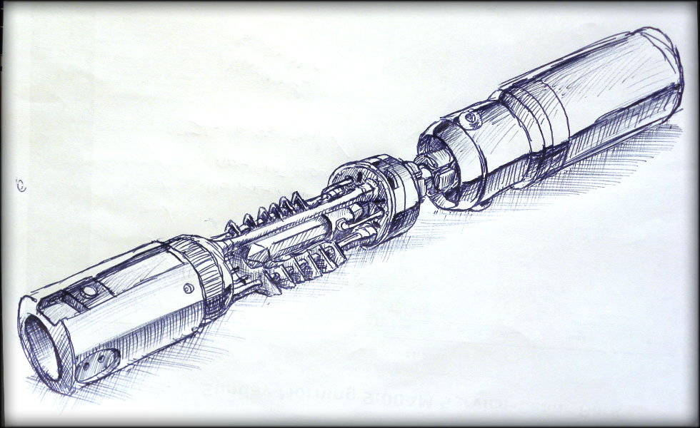
Well folks, after about a week of trying to think of how to interface my switch and detachable blade to the rest of the chassis, I think I have it. Last night I stopped the mental gymnastics and actually started making the interface point a reality.
053.jpg

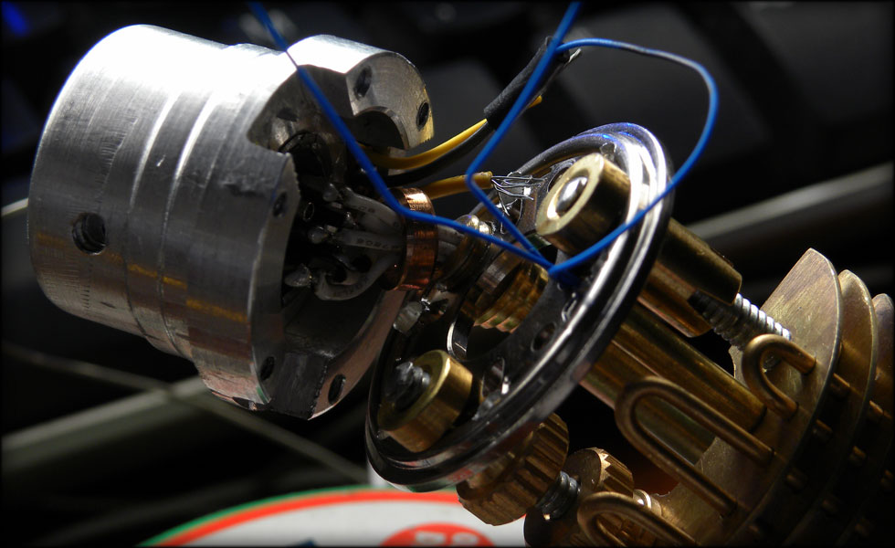
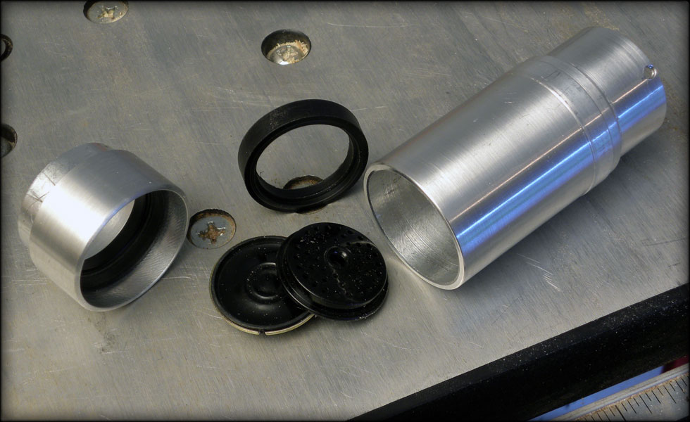
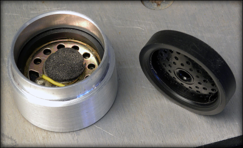
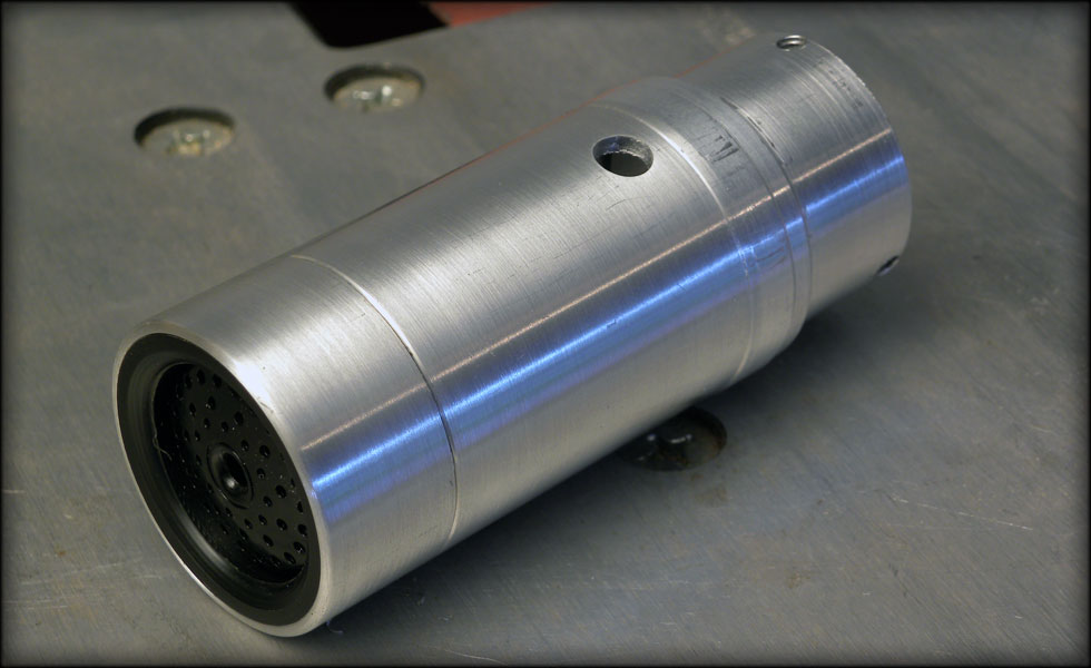
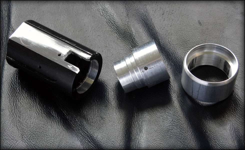
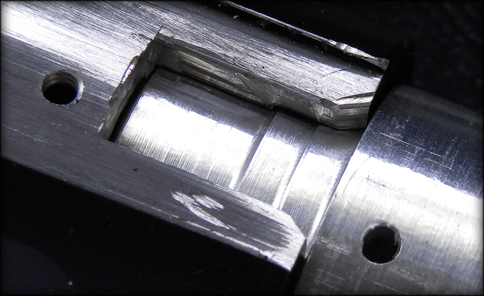
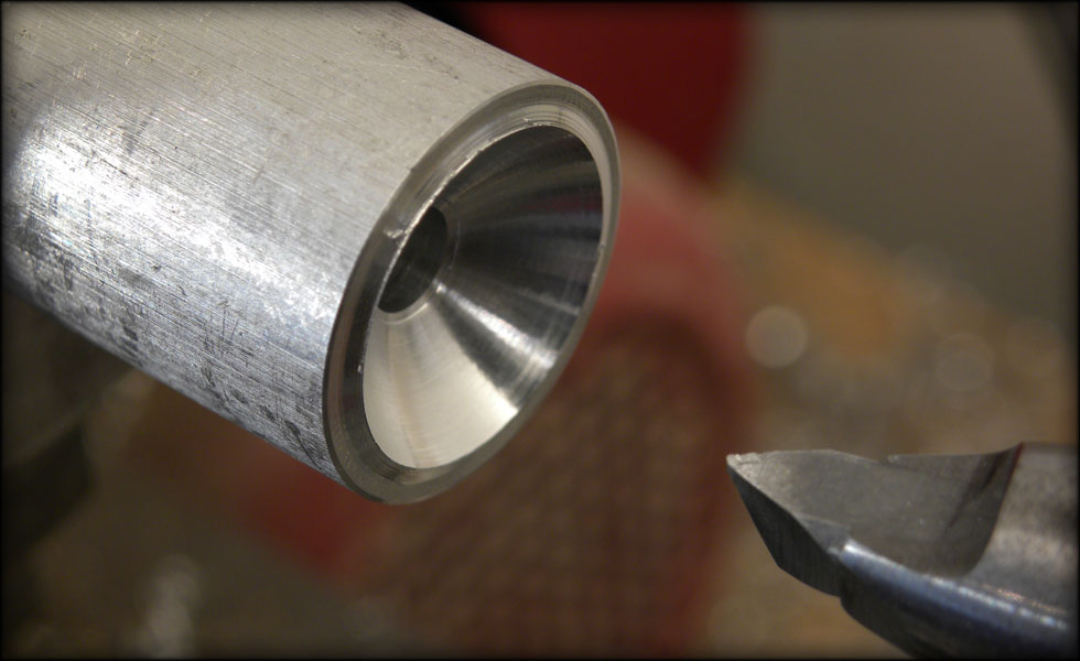
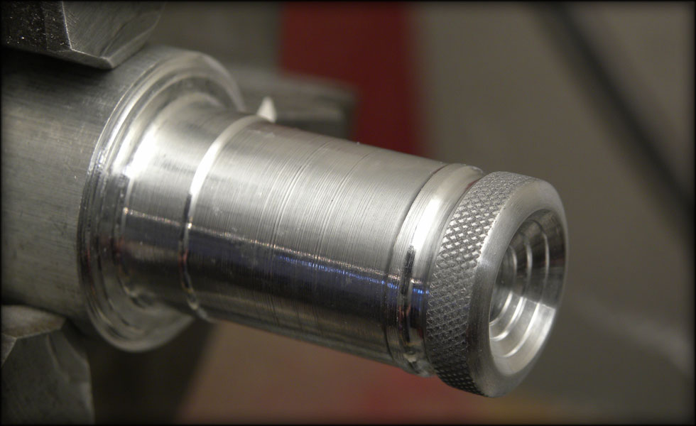
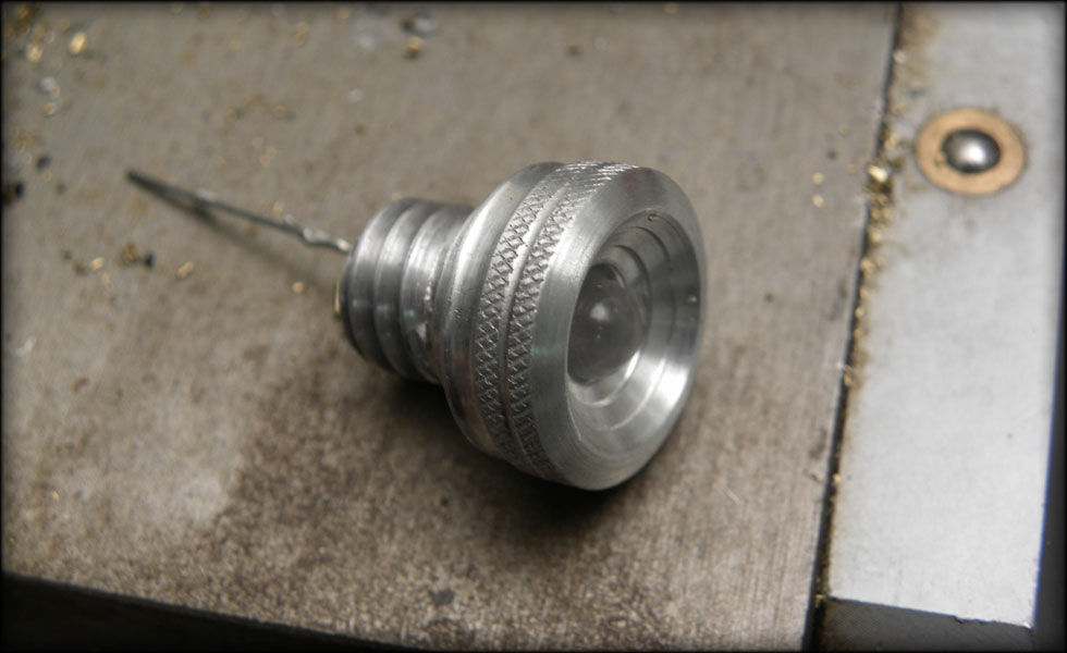
Here we have my blade adapter, modified with a big notch and filed down in the top channel to be as flat as I can make it. Also visible is my aluminum plug that inserts into the adapter, and outer collar that fits the harddrive platter retainer from the chassis, and also perfectly fits the inside diameter of the graflex housing.
054.jpg

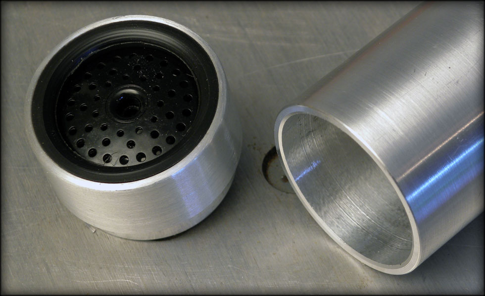
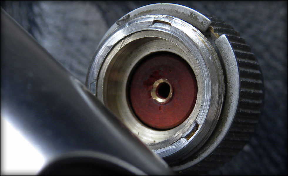
The plug precisely fits snug into the blade adapter. This is where the end of the chassis will plug into the blade adapter and through this, on to the blade and plug.
055.jpg

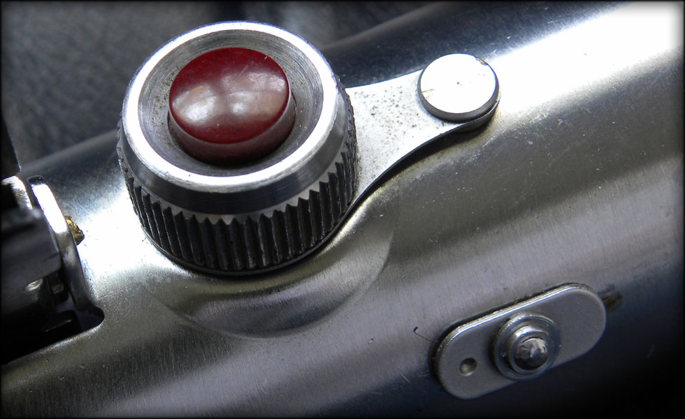
Why the notch? Well, My Pololu switch, while awesome, does need connection back to the rear of the chassis, and having a quick disconnect wire that I plug in and stuff into the thing isn't the slothfurnace way.
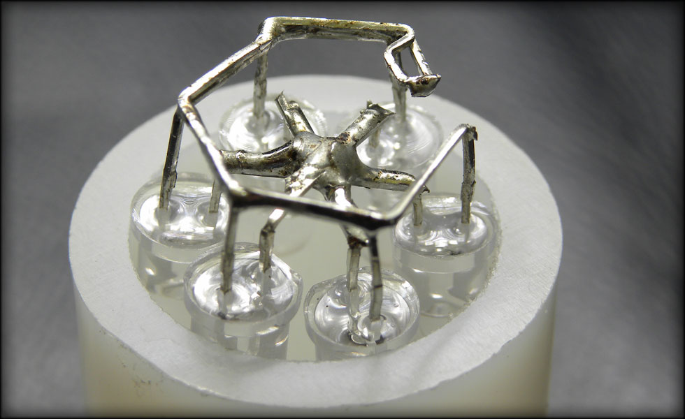
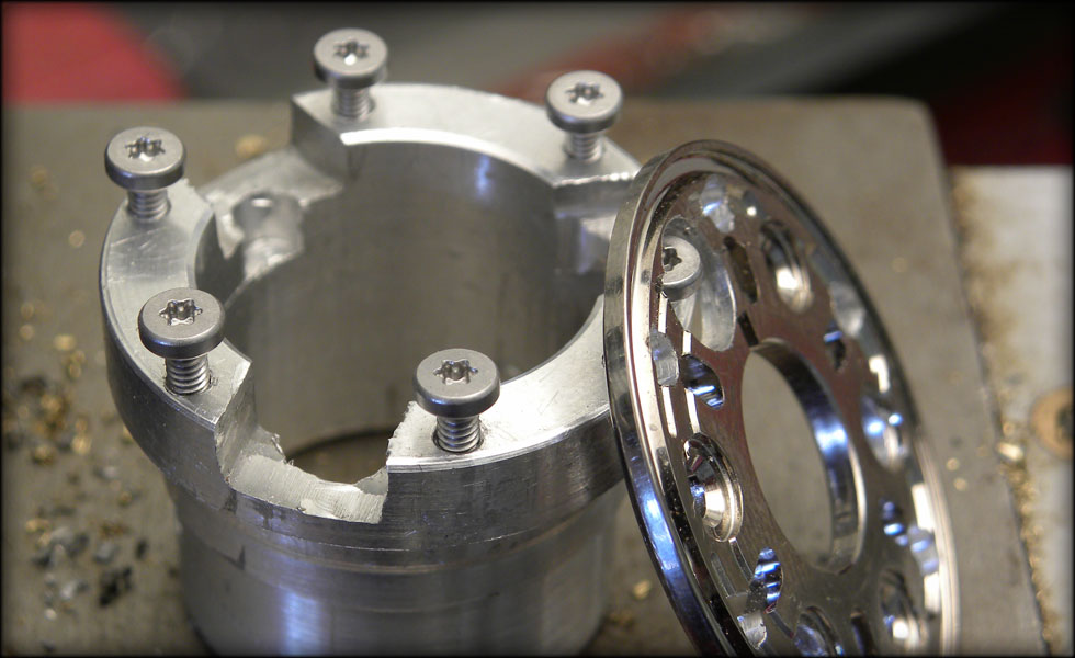
So, we make custom parts, and create a multifunctional feature. This notch both serves to index the angle of my chassis to the saber itself, therefore keeping things in line, and to allow me to use a 3 contact plug (mounted in the chassis front piece) to connect the Pololu to the back of the saber.

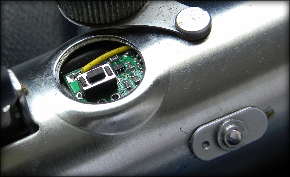
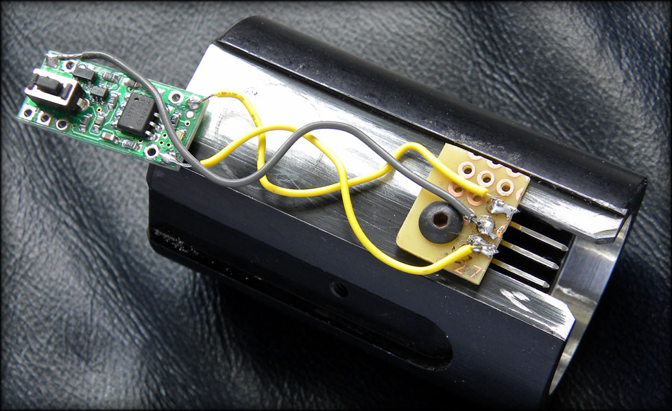
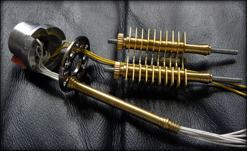
The reason for the long wires, is so that I can push the Pololu out to the end of the channel and drop it down so it all fits when I insert it into the graflex top end. The height of the Pololu wouldn't let me mount it in the channel, I have to set it out and down, slide it all in, then once the Pololu reaches the switch hole, I raise it up, and slide the adapter on in under the switch. The wires are coiled that way so that they compress into the adapter channel when the switch board gets closer to the perf board. It BARELY fits. nice and snug.
056.jpg

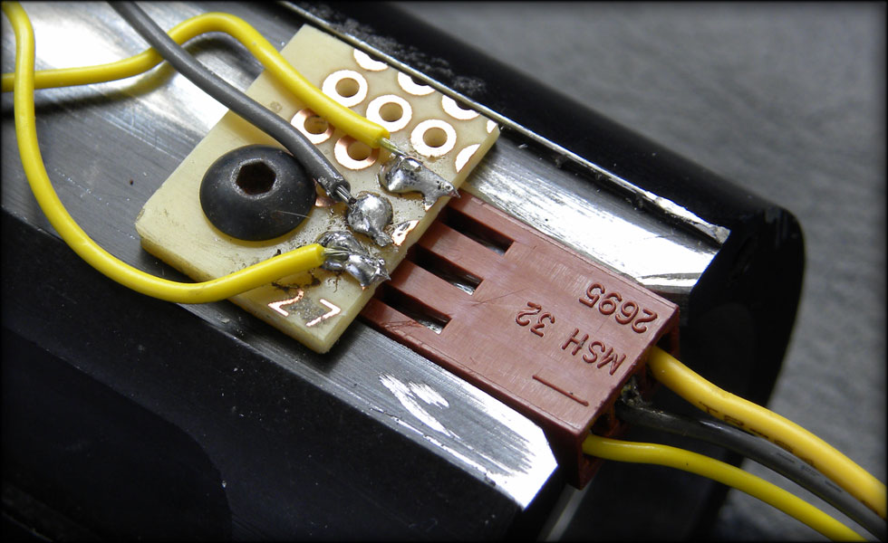
This was a scrap piece of perf board and a small screw I had in the parts bin. The flatness of the perf board across the top of the adapter channel keeps the plug stationariy up and down, and the notch keeps it stable left and right. I'll notch out on my aluminum end piece to accept the plug, and when it all fits together, it should be nice and snug.
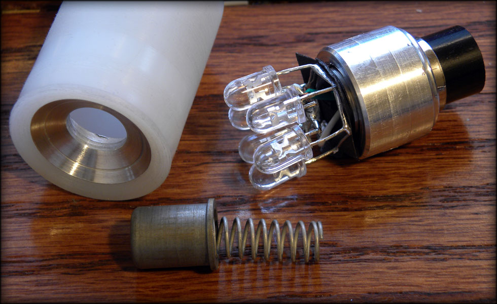
Next up, the actual blade and the non blade light up insert interface. I have the parts, but no pics yet. I need to test it first.
 
Last edited:
What are the dimensions of the aqua aura crystal you're using?

It's 1/4 inch by 1.5 inches roughly...

Well, it's been a while since I have posted, but here's some updates.
Last week I spent a ton of time on the plug that goes into the blade adapter and interfaces with the detachable blade. More on that later, but here's a few pics.
057.jpg

When the blade is not in the saber, I have a 1" to 3/4" blade stepdown adapter as my plug. Inside that I have soldered 6 Mako V3 LEDs to make the ring illuminate when it's turned on. Not quite finished with that part yet though.
058.jpg

Here I have set up my radius cutter to do the radius for the collector on the inside of the chassis, positioned above the crystal.
059.jpg

Here you see my radiused inner surface, the hole will be for another Mako V3 LED.
060.jpg

Here I have knurled a section, radiused the outer edge, and begun trimming down the back of the piece so I can part it off and thread it. This will hold the top harddrive platter retainer plate to the machined adapter plug. That might not make sense now, but once I get pics made of that piece it will all be clear.
061.jpg

Here's the custom bolt finished, threaded for 3/8, hollowed for the LED, and cut down so it fits the inner hole of my harddrive platter retainer plate.
 
excellent work :love, grats :thumbsup


Thanks!

Here's a couple pics on a major update,
062.jpg

This was the result of some very tedious headscratching. The joining of the chassis to the actual adapter plug went through heavy revision until I finally found a way to do it with the space I had left that also let the unit be strong.
I decided to take the very heavy risk of drilling and tapping six 2-56 holes through the retainer plate into my plug housing, then using scrap harddrive screws to mount the retainer plate to the plug. I had no room to use the custom LED bolt collector I had machined, so this is how it has to be.
063.jpg

And here I am testing my wiring harness for fit and finish, all the wires fit, and I also took the last four radiator plates, and for three of them drilled a hole that will accept the shock sensor, and the very last one, a hole that fits the wires for the shock sensor. I like having the shock sensor embedded here, as it adds a bit of interest, and gets it away from cramped spaces while also keeping it rigid.
The switch wires run through holes in the radiator as well, the length of the chassis.
 
Just finished reading through this..
Truly amazing work slothfurnace! :eek

Very interesting project..

Can't wait to see the final saber..

Keep up the good work :thumbsup
 
Any updates yet?

-Chaim


The final details are so slow. The last ten percent is the hardest...

064.jpg

Well, tonight I had to solve a lingering problem with my crystal mount.
The LED matrix had a kind of sloppy circular positive lead ring. In addition to being sloppy, it tended to ground out against my support pillars after I added the thicker machined brass trim pieces.
065.jpg

To solve it, I tossed the Mark I LED matrix in favor of the Mark II. A triangular hot lead, with inverted LEDs, passing the hot lead under the mount, against the crystal itself to add stability to the crystal.
This also is a tighter, closer in setup, and after noodling with how exactly to do it, I finally just bent and soldered everything with the crystal installed, thereby making sure it all fit. I inverted the LEDs so I could pass the ground Leads up into the mount, grounding against the body of the mount, and hiding them as well.

066.jpg


067.jpg
 
Last edited:
069.jpg


Tonight I spent ironing out a few things with wiring, getting ready for the final assembly. Hopefully I will only have to tear it down and rebuild it all a few more times.

068.jpg


I also spent some time on my blade adapter plug, for when the saber has no blade installed.. These pieces are a 1 inch to 3/4 blade diameter reducer, sloped to fit the machined insert, which holds the vintage bulb contact point from the Graflex. It is suspended by the original spring, which sits atop the six Mako V3 LEDs. I connect everything through the Graflex Blade adapter via an 8 pin DIN plug.


070.jpg


And a test lighting of the lit adapter plug. You'll notice the large gaping hole in the bottom of the graflex blade adapter. I hollowed this out to accept the original glass eye, as I was unsatisfied with the glass eye thumbscrews available. Plus it lets me put a section of Anode mesh from a broken nixie tube behind the glass and let the blue light come through.

071.jpg


The original glass eye mount also serves as a large thumbscrew to tighten against the blade plug or blade when it's installed, to keep it all nice and snug.

I do notice I have one more issue with my crystal mount, it's not coming on with the rest of the saber, due to a grounding issue. It's not a short, but it was an oversight on my part about how the board works. Right now I have t he crystal LEDs grounding through the whole saber. Which works when it's out of the body, but when it's all installed, it doesn't work right with the recharge port, etc. that does actually ground back to the battery pack.

So one more teardown to fix that, and we're looking at home stretch, folks.
 
Back
Top