Slothfurnace's ANH Luke Graflex Saber chassis. PICS, Step by step.

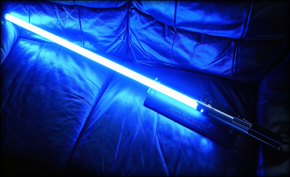
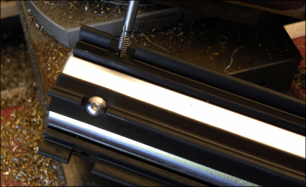
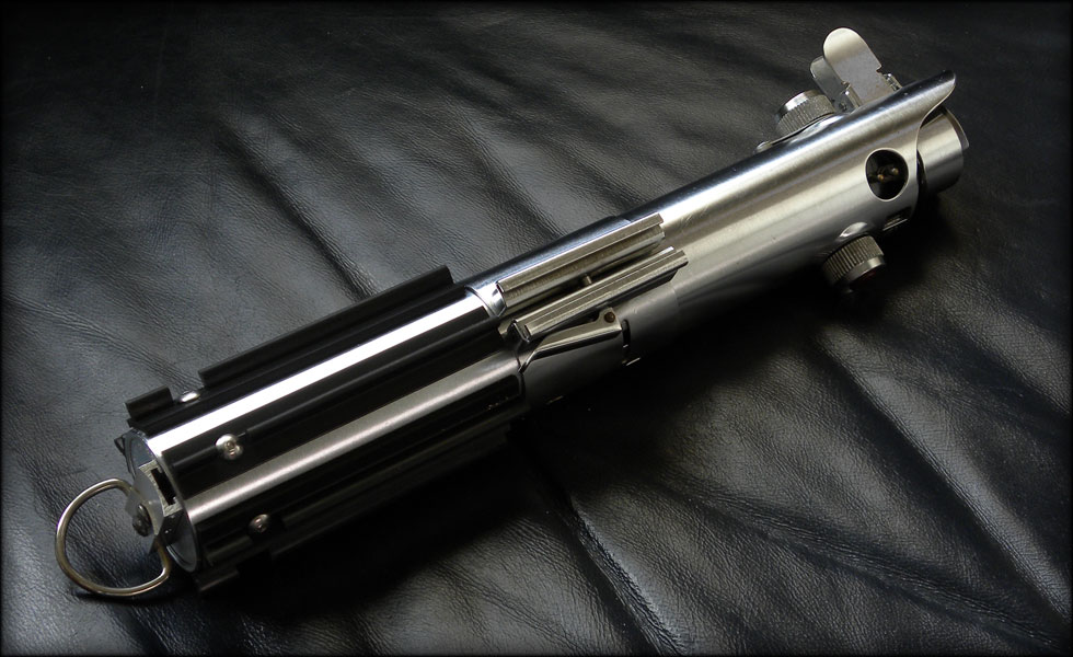
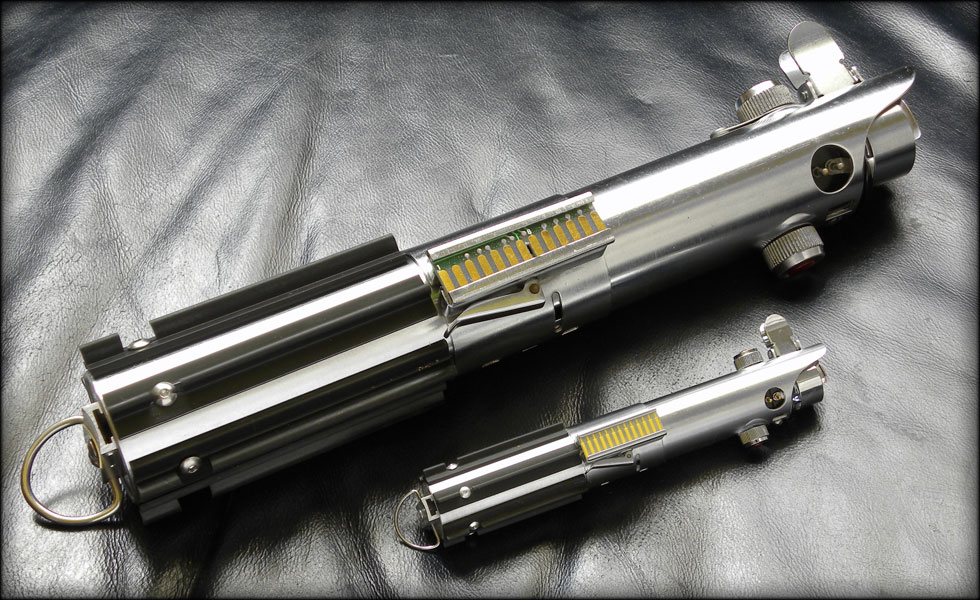
Did a little work tonight on my blade, I think I finally finished this step up. I had to shorten my blade a couple inches, and then I needed to finish my plug.


094.jpg


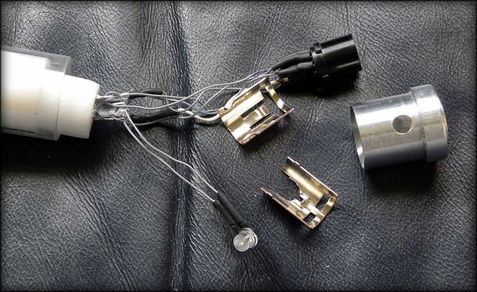
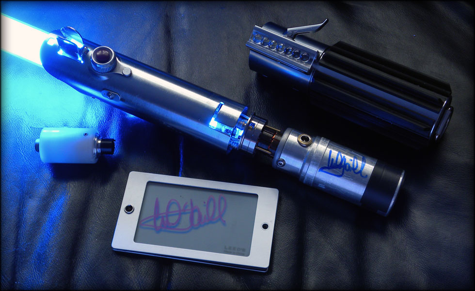
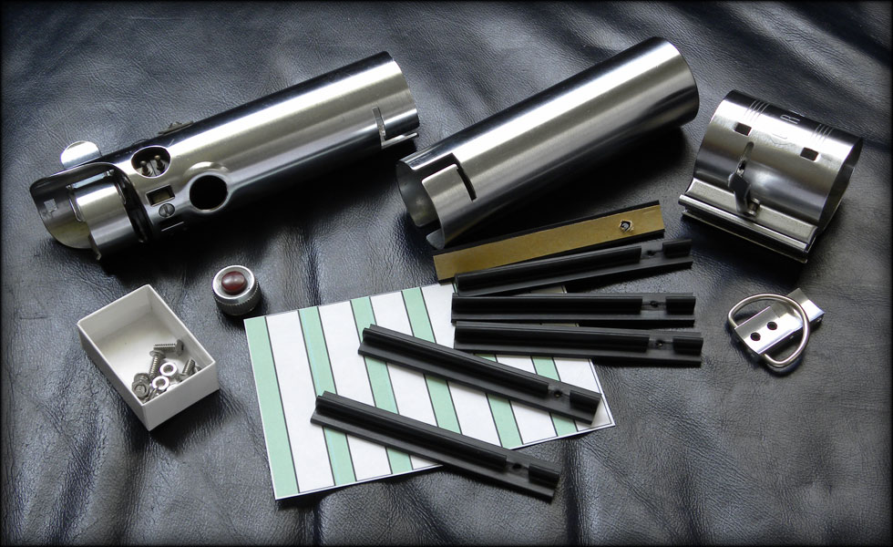
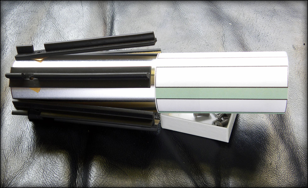
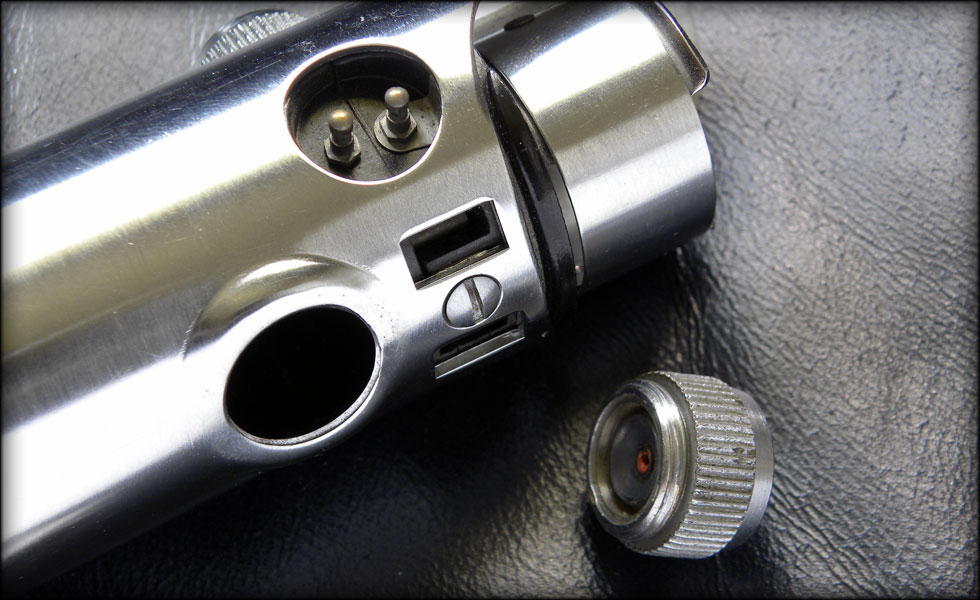
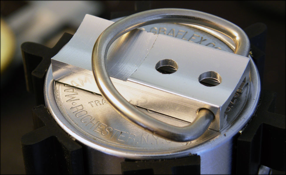
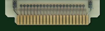
Here's a shot of the blade plug setup. I have my LED string in there, with one LED off the base, with wires, bent and cut down to fit the hole I drilled in the base DIN plug adapter. This allows me to shine a very bright light into the graflex glass eye. Otherwise, I wouldn't be getting any light in there due to the adapter covering up the glass eye port. I also had to drill and notch the DIN plug retainer bottom half to accept where my LED is sitting. It's all very close quarters in there, but it fits and works fine.

095.jpg


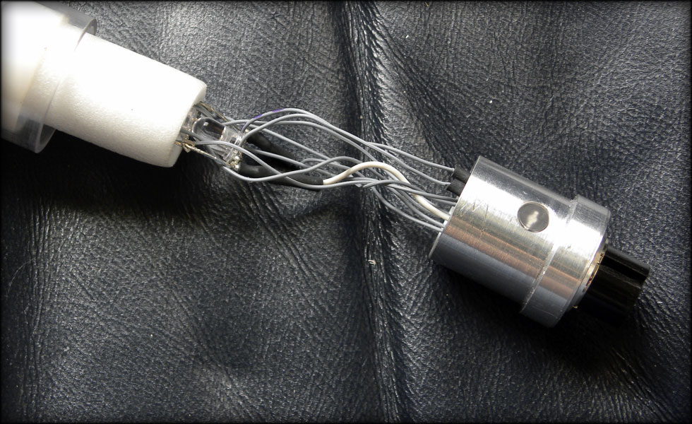
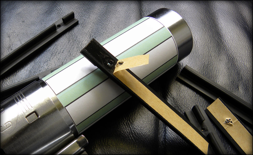
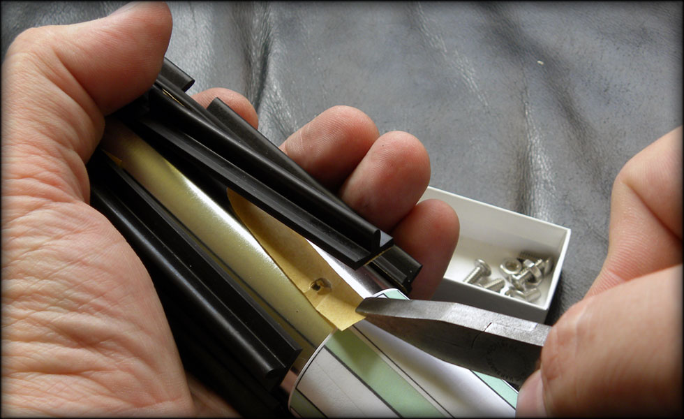
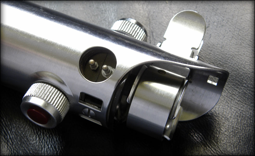
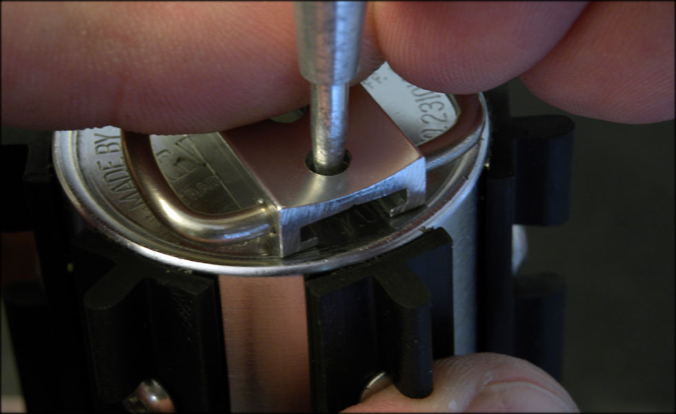
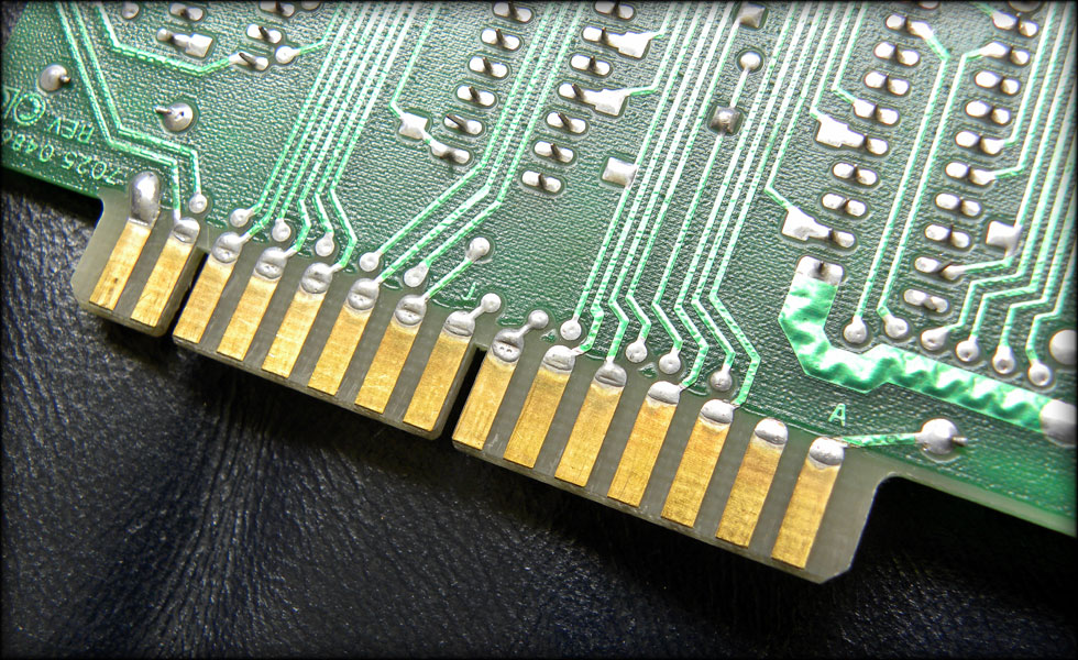
Here you see how it goes together. The LED is cut flush to the inner diameter of the blade plug. The wire slack will coil up inside the adapter.

096.jpg


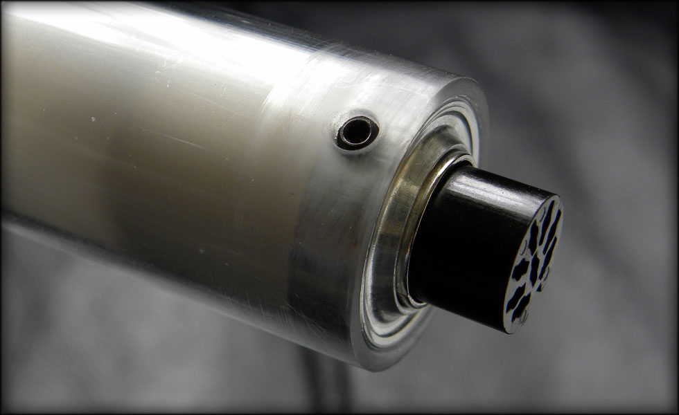
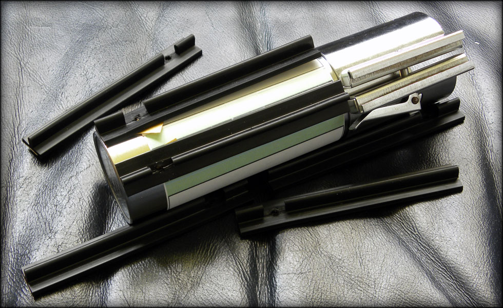
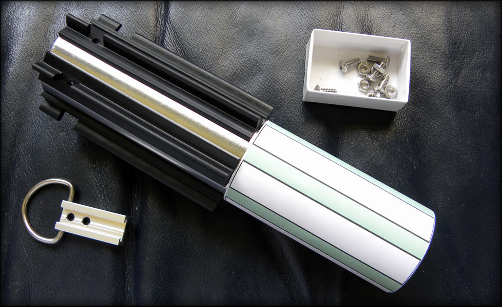
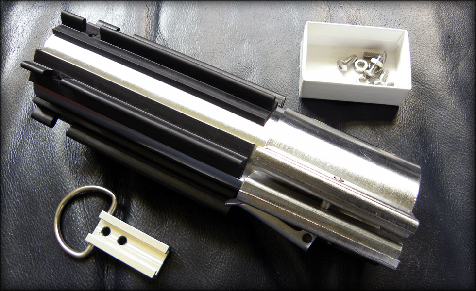
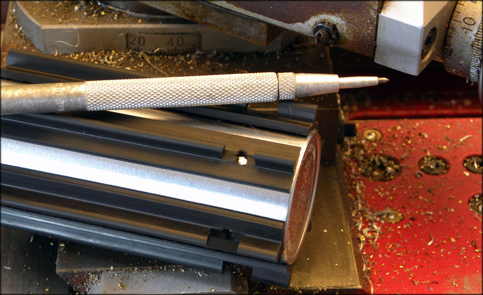
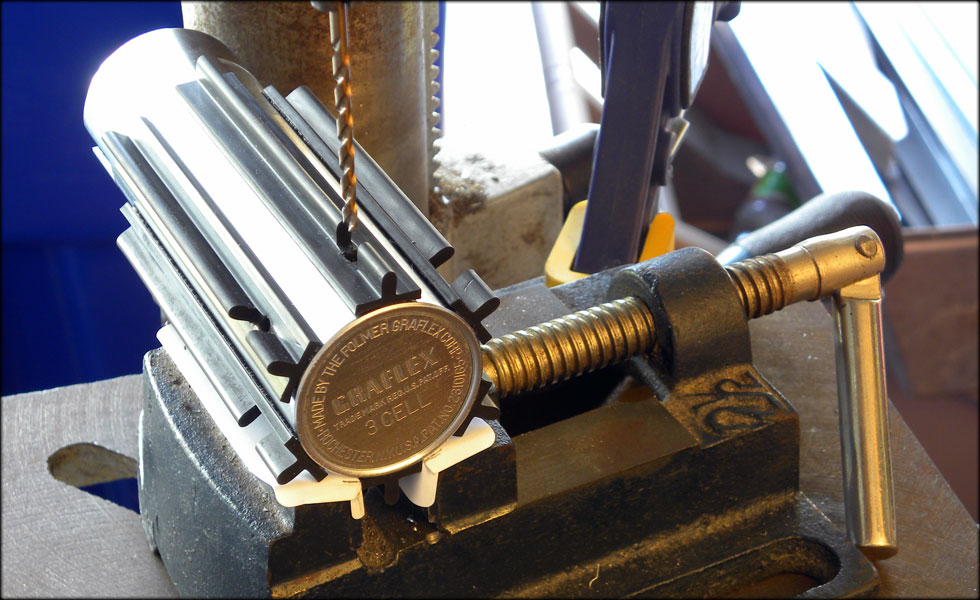
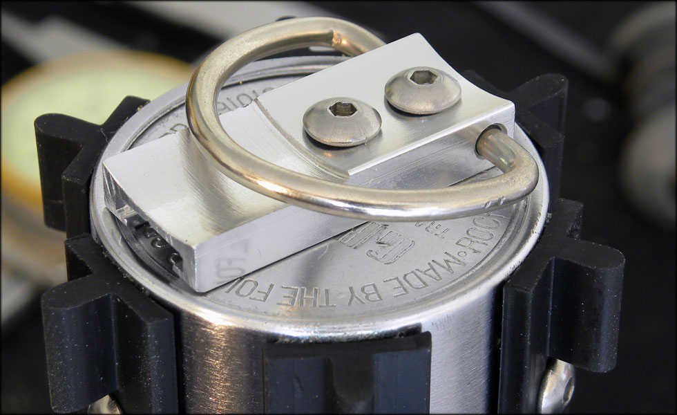
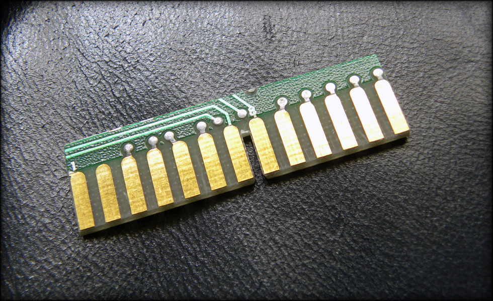
Here is the setscrew that keeps it all together, this keeps the plug in the blade adapter, and the adapter in the blade.

097.jpg


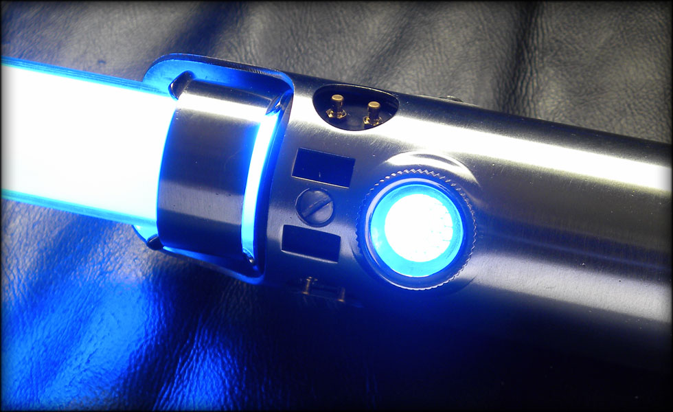
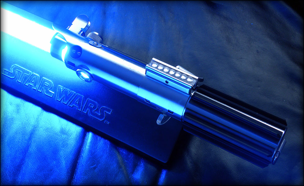
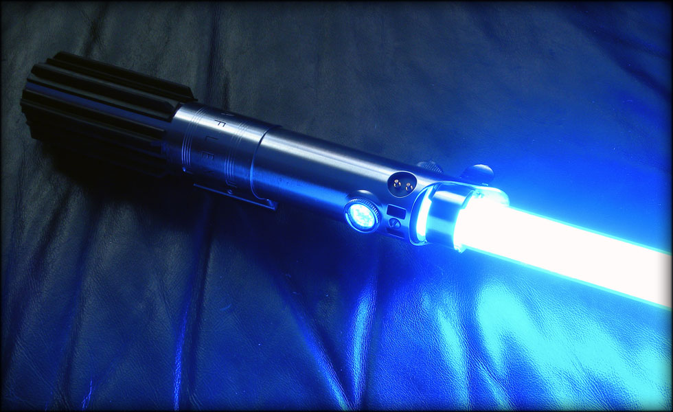
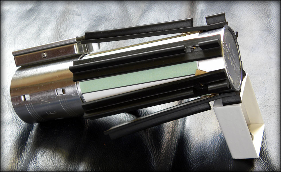
And now for what I like to call "a little moment of truth." It's when you get it all together and turn it on and see your hard work pay off. It's when you have your fingers crossed and flip the switch.

098.jpg


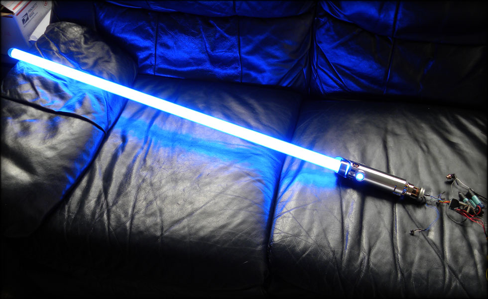
I have a little more work to do on the battery canister, I need to make absolutely sure everything is isolated, stable, and good. But I am very very close.
 
Hey there,

I've got a real vintage MPP here that could do with a little tune up/upgrade . . . the Slothfurnace way :love

-Chaim
 
And now we come to the ESB hilt that will go with my ANH hilt. I debated making a new thread for this, but for now, I'll keep it all in one place.

001.jpg


This saber is going to be a lot easier to make than my New Hope graflex. I will make it so that both the ESB and ANH sabers can share the same internal chassis. I will most likely mount them both on a display with one having the expanded look with the chassis in it, and the other saber displayed closed, beneath it. I have many of the parts ready to go for this, the original Graflex flash gun, the Kobold replica D ring assembly, the 6 notched grip sections from Blast Tech, and an extra vintage Graflex red button assembly.

002.jpg


Since I had the parts for this, I thought I'd start with the grips. I made a grip alignment template in Photoshop, printed and cut it out. I wrapped it around the base handle and taped it to itself so I could slide it off. More on that later.
Here's the way I do it. This is my way, not the only way, but it's what works for me. Before you start, CLEAN the graflex handle with something like rubbing alcohol or degreaser. This is very important to get a good stick on the grips. Then be careful not to touch it after that. Then, align your template where it needs to be, and don't move it. I try to leave around a half inch above the template clear, so I have something to stick the back of the grips to. I peel the first little bit of the adhesive backing off the grip, and fold it to the side. This is important later.

003.jpg


Now I very carefully adhere the grip section that's exposed to the metal base, making sure my peeled section is accessible to one side, and that my grips are aligned to the template as accurately as possible.

004.jpg


Making sure that they are evenly spaced around AND up and down, and that my template hasn't moved, go ahead and attach the rest of the grips in that fashion. It will be very cumbersome, so you have to be careful.

005.jpg


Now the hard part. CAREFULLY slide the template down JUST past the ends of the grips, without rotating it. If you got your template on tight enough, it should smoothly slide down, and stay in place. Also, make sure you haven't accidentally stuck your grip sections TO the template, that's why you only peel a small bit of the adhesive backing off.

006.jpg


Now the fun part! Hold tightly with your thumb to the stuck section of grip, and with needlenose pliers, reach under the grip and grasp that folded piece of backing. Slide it carefully down away from your thumb, and with a finger (if you can) keep the grip from snapping to the graflex until you're ready to push it down.

007.jpg


Once you get the adhesive backing off, line your grip up with the lines on your template, and press down. You may have to lightly adhere it, look, reposition, etc, before you finally press it for good.

008.jpg


Once you have all your grips done this way, use opposing force on them to press them. Meaning, pinch each side of one grip with your thumbs, and each side of the opposite side's grip with your fingers, and press hard to secure the adhesive. Once done, slide your template off, and attach your clamp. I'll get into the screws that go into the notch a little later.

009.jpg


While I have my parts out, I thought I'd go ahead and remove the glass eye mount, and replace it with the extra red button from the other busted Graflex top I found on ebay. This is easy, the button just unhooks from the pull tab metal retainer, and the threading is the same, so it will screw right into the glass eye hole.

010.jpg


Like so.
 
011.jpg

Here we have the pieces together, sans D ring and grip screws. Along with it's older brother.
012.jpg

Speaking of grip screws, I believe I will add those now. First, I had to trim out some of the rubber around the holes drilled in the grips. They were not perfectly aligned left to right, so I had to widen them slightly. I also used my scribe to dot in where my centerpoint for the holes will be, it's that barely visible indentation on the metal under the rubber. This is where my screw hole will be drilled, and I made sure they were the correct distance to the back of the hilt with my micrometer.
013.jpg

Now comes a picky step, making sure the holes are drilled properly each time. I set my clamp to close up just outside a grip strip, and put some tape down to keep things from scratching. The metal tube sits on the vice claws, and that keeps it level, and aligned. On my tape, I marked the spot where I slide the grip back to with a pencil.
014.jpg

Once the holes are drilled, and all the shavings cleaned off, I tap them out with the 6-32 tap, making sure to keep it level and straight. One tip here is to not let it tap all the way, to let the screw work a little harder to get in there in the end, that is if you're doing what I am doing, and not using the nuts that came with the screws. The reason I am doing that is that my chassis from the ANH saber will fit in here, and I can't have all those nuts and screws taking up room, or else the battery can won't slide in. This also means I have to shorten my screws at some point, but that's not too hard.
015.jpg

Once I have the grip screws tapped and installed, I come to the replica Kobold Flash D ring assembly. This piece almost fits flush against the hilt, but I will have to file off the corners a bit to get it to fit better.
016.jpg

Taking a pic of this was hard, so parden the slight blurriness, but this is how I mark where the holes will be for the D ring mount. I press in with my scribe to get it "ballparked" then go in and measure and make corrections. Once I am satisfied with where my holes will go, I drill, tap and install the D ring mount.
017.jpg

I had a minor calamity when assembling this, but nothing a slight burr off with the dremel can't fix. But word to the wise, measure twice, cut once, MAKE SURE what you're about to do is lined up properly. I accidentally indexed my D ring incorrectly, but it was fixable without any exterior clue as to what happened.
018.jpg

Here is a shot of the hilt with most of the exterior pieces installed. I lack the PCB Card strip that goes in the clamp, and once I get a little further along, I'll order the blade adapter and machine it to fit my chassis, get a new pololu latching switch for this setup, and this little fellow will be done! (Until I decide to do more) Stay tuned, more to come!
 
Impressive, most impressive!

Love the work you've done! I just received my 3 cell bottom today and just awaiting my ANH kit, should arrive before Saturday. I want to have a similar result of the internals and blade at some point!

Tim


graflex3.jpg

graflex4.jpg
 
Hey Brad,

Perhaps you could make your own ESB PCB Card since
it's only 13 thin golden strips which taper down into 13
even thinner silver strips on a 2" piece of plastic board?


HP-44BusTypeComputerCardEdgeConnect.jpg

(photo courtesy The Parts of Star Wars website)


And when you're done perhaps you could 'replicate' one for
me too :love it's the only real piece missing from my Luke ESB.

-Chaim
 
Last edited:
Hey Brad,

Perhaps you could make your own ESB PCB Card since
it's only 13 thin golden strips which taper down into 13
even thinner silver strips on a 2" piece of plastic board?


HP-44BusTypeComputerCardEdgeConnect.jpg

(photo courtesy The Parts of Star Wars website)


And when you're done perhaps you could 'replicate' one for
me too :love it's the only real piece missing from my Luke ESB.

-Chaim

I made one before, cut a section out of a PCI video or network card from a computer, and filed/sanded edges down to fit.

Tim
 
I made one before, cut a section out of a PCI video or network card from a computer, and filed/sanded edges down to fit.

Tim


Hi Tim,

Any pictures of it perhaps? It's hard to find a computer card with 13 straight lines in a row which taper into smaller lines.

-Chaim
 
Hi Tim,

Any pictures of it perhaps? It's hard to find a computer card with 13 straight lines in a row which taper into smaller lines.

-Chaim


This is the best I could find...

019.jpg


Well, the other day, I was digging through my junk bin and ran across this Sun microsystems PCboard from 1984. I had salvaged this and several other like it from an old auto diagnostic machine they threw out at the auto shop in high school. Meaning, I have been hanging on to this since 1993. Not sure why, but I am glad I did, because this particular PC board had the required wide connection strips that would put 13 evenly spaced in my graflex clamp. The original prop had a section of PC board from a Hewlett Packard I/O BUS card with these wide strips tapering to thin narrow traces. The original had them tapering straight. This card, unfortunately doesn't have straight traces coming off the connector points, but it will do untill I find another one, and best of all, it is free!

020.jpg


A quick visit to Dremel Land and I have the required 13 strips cut out. I know the original didn't have the green soldermask silkscreened onto it, but this will work for now, like I say.

021.jpg


And here it is installed, next to the licensed Master Replicas scaled version of this saber. I am pretty darned close...
 
Mine was similar to the MR scaled version too. Just an old PCI card I think it was from.

Tim
 
Back
Top