JetEngineProps
Member
So I bought an MK9 engine from a government auction up here in Canada. This is a bit of a write up on the adventure!
Our Science and Tech museum was clearing out their warehouse, where they had had it in storage since the early 70’s. It was a factory MK9, not an upgraded MK8. The journey begins with the pickup. They loaded it on to my trailer with their forklift, and the pickup went fairly smoothly.

So first off, if you’re going to do something like this, I highly recommend having a plan on how to move the engine. The auction listing gave an estimate of ~1400lbs, no easy feat to move! I brought it to my dad’s farm workshop to work on. Tractors for the win.
.jpg")
I’ve got a video of the engine before dismantling at
.
And so the work begins, starting with removing all the hoses. I was able to remove pretty much everything with a metric wrench set. Before being able to remove the hoses, it turns out almost every fitting was wired together, slowing down the process a bit.

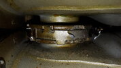
After the hoses were disconnected, unscrewing the outer chambers from the ring frame was next. I think this is new for the MK9, and this really slowed down the disassembly. Each outer chamber had ~10 of these nuts, and they all had a locking washer like thing, preventing the use of a socket wrench. I used a 9mm wrench on these, but I found the best method to prevent stripping was to use a small vice-grip to get it started first, then use the wrench to finish it.


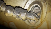
Next, was splitting the balance pipes. They have this band to lock the coupler pieces together. It’s fairly soft metal, and I found twisting a flathead screwdriver in there was enough to eventually get the band to break (there’s probably a better way to do this).

After the band is removed, I had to figure out a way to split the halves. I found the best way was to use a pair of large vice grips and to tap on the other side with a hammer and flathead, unscrewing the two sides. Do this on both sides of the chambers, and it’s now disconnected from its neighbours.


Finally, there’s two screws holding the chambers to the fan vent. Using a 11mm and a 12mm wrench I was able to remove these fairly trivially. With the help of a crowbar, the chamber is free!


I’ve noticed that the outer chambers are stamped with numbers and the serial of my engine.

Rinse, repeat 8 more times.

More pictures at: pictures - Google Drive
Lessons Learned
So a factory MK9 has a few variances from the MK8.
1. As mentioned, the outer chambers have an extra lip with the extra bolts.

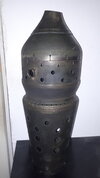
2. The flame tube has a variance in the bottom hole pattern, making it different from the IG-88/IG-11 head on the bottom.

.jpg")
3. My MK9 didn’t have the fabled correct balance pipes. It had the smaller version. You should be able to tell from the outside, if somehow another engine pops up. The ‘correct’ BP’s would have a bigger diameter than pictured.


Future work
My goal was to get a flame tube and an outer chamber to do castings from. While the tube doesn't have the correct hole pattern, the tube will still work fine for this purpose. Just need to add in two bands, cast it smooth, then cut out the bigger holes from the cast copies. Might even be easier to make the master mold from this one over the larger holes when doing the clay. I have a CNC milling machine that I plan to program to cut out holes from the rotomolded copies.
I plan on selling the other sets of balance pipes and extra flame tubes. Still need to remove them from the outer chambers, and figure out what a fair price would be. They have a pretty awesome patina, and are from the correct era. Should make pretty sweet lamps, or even masters for casting.
Our Science and Tech museum was clearing out their warehouse, where they had had it in storage since the early 70’s. It was a factory MK9, not an upgraded MK8. The journey begins with the pickup. They loaded it on to my trailer with their forklift, and the pickup went fairly smoothly.
So first off, if you’re going to do something like this, I highly recommend having a plan on how to move the engine. The auction listing gave an estimate of ~1400lbs, no easy feat to move! I brought it to my dad’s farm workshop to work on. Tractors for the win.
I’ve got a video of the engine before dismantling at
And so the work begins, starting with removing all the hoses. I was able to remove pretty much everything with a metric wrench set. Before being able to remove the hoses, it turns out almost every fitting was wired together, slowing down the process a bit.
After the hoses were disconnected, unscrewing the outer chambers from the ring frame was next. I think this is new for the MK9, and this really slowed down the disassembly. Each outer chamber had ~10 of these nuts, and they all had a locking washer like thing, preventing the use of a socket wrench. I used a 9mm wrench on these, but I found the best method to prevent stripping was to use a small vice-grip to get it started first, then use the wrench to finish it.
Next, was splitting the balance pipes. They have this band to lock the coupler pieces together. It’s fairly soft metal, and I found twisting a flathead screwdriver in there was enough to eventually get the band to break (there’s probably a better way to do this).
After the band is removed, I had to figure out a way to split the halves. I found the best way was to use a pair of large vice grips and to tap on the other side with a hammer and flathead, unscrewing the two sides. Do this on both sides of the chambers, and it’s now disconnected from its neighbours.
Finally, there’s two screws holding the chambers to the fan vent. Using a 11mm and a 12mm wrench I was able to remove these fairly trivially. With the help of a crowbar, the chamber is free!
I’ve noticed that the outer chambers are stamped with numbers and the serial of my engine.
Rinse, repeat 8 more times.
More pictures at: pictures - Google Drive
Lessons Learned
So a factory MK9 has a few variances from the MK8.
1. As mentioned, the outer chambers have an extra lip with the extra bolts.
2. The flame tube has a variance in the bottom hole pattern, making it different from the IG-88/IG-11 head on the bottom.
3. My MK9 didn’t have the fabled correct balance pipes. It had the smaller version. You should be able to tell from the outside, if somehow another engine pops up. The ‘correct’ BP’s would have a bigger diameter than pictured.
Future work
My goal was to get a flame tube and an outer chamber to do castings from. While the tube doesn't have the correct hole pattern, the tube will still work fine for this purpose. Just need to add in two bands, cast it smooth, then cut out the bigger holes from the cast copies. Might even be easier to make the master mold from this one over the larger holes when doing the clay. I have a CNC milling machine that I plan to program to cut out holes from the rotomolded copies.
I plan on selling the other sets of balance pipes and extra flame tubes. Still need to remove them from the outer chambers, and figure out what a fair price would be. They have a pretty awesome patina, and are from the correct era. Should make pretty sweet lamps, or even masters for casting.
Attachments
Last edited: