You are using an out of date browser. It may not display this or other websites correctly.
You should upgrade or use an alternative browser.
You should upgrade or use an alternative browser.
Revell Razor Crest Lighting WIP
- Thread starter Antsnest
- Start date
Another small update - I made a couple of nav light "nipples" for the engines- these go on the end of a .75mm fibre and the tip will protrude up from the inside of the engine cowl top and bottom. These are just test pieces printed with the grey resin that was in the printer, but will ultimately be printed in clear (although plenty of light comes through the grey!). I also made a connector to mate the 2 fibres to a 3mm LED easily.

Overdue update - trying to get this project back on course...
Decided it was going to be easier to remodel the whole cockpit console with some built-in holes for 0.25mm fiber than trying to drill them all neatly in the kit piece - and anyway the detail is a bit soft.
Working over the weekend in a true iterative design process, I've been blocking in the shapes and adding the detail in a number of successive prints. I started copying the kit piece but when I went and looked at references you can see it's not very accurate at all and the whole center screen is missing, the controls are wrong and there's no shiny knob at all!


Center console added, screens opened up.

The plan is to make clear inserts for each screen and light them with their own LED. There's still more detailing to add - the 3x3 grid of holes on the right hand side was just a test to get the sizing right and will be replaced. A couple more sessions should have it done.
I've also printed a new rear bulkhead light unit with space for LEDs behind. I didn't think the detail would actually print because it is so fine, but it came out perfectly!

Decided it was going to be easier to remodel the whole cockpit console with some built-in holes for 0.25mm fiber than trying to drill them all neatly in the kit piece - and anyway the detail is a bit soft.
Working over the weekend in a true iterative design process, I've been blocking in the shapes and adding the detail in a number of successive prints. I started copying the kit piece but when I went and looked at references you can see it's not very accurate at all and the whole center screen is missing, the controls are wrong and there's no shiny knob at all!
Center console added, screens opened up.
The plan is to make clear inserts for each screen and light them with their own LED. There's still more detailing to add - the 3x3 grid of holes on the right hand side was just a test to get the sizing right and will be replaced. A couple more sessions should have it done.
I've also printed a new rear bulkhead light unit with space for LEDs behind. I didn't think the detail would actually print because it is so fine, but it came out perfectly!
Clear parts for console screens and cargo bay light units printed. Plus a few spares for experiments

Console painted up to see how it looks. The "shiny" knob is not installed yet due to fragility.

Quick test with screens and fibers installed - I ran out of fiber & only managed one half! 15 lights in the left side, 23 in the right.

Console painted up to see how it looks. The "shiny" knob is not installed yet due to fragility.
Quick test with screens and fibers installed - I ran out of fiber & only managed one half! 15 lights in the left side, 23 in the right.
Ok , been faffing about with this project for far too long. Time to take the bull by the horns and start cutting plastic!
The front lights will be lit with a couple of 1mm fibres, connected to a single red LED in the belly of the craft. It was necessary to
Dremel out a channel to allow the fibres to fit through the lowest point where the floor plate rests. There's room for the LED in the
natural void where the bottom 'stand' plate sits.

A small channel was made in the floor and inside panel to allow the LED wires to pass up to the driver PCB.

The nav light 'bulbs' were printed in clear and glued to the ends of some 0.75mm fibre

Holes were drilled in the top & bottom of the engine cowls for the nav lights - these were eyeballed from stills from the show. The nav
lights fit into these from the inside.


An engine light holder ring fits into the front end of the engine and holds the engine LED at the optimum place for the diffuser. It also
holds the nav light LED-to-fiber adapters just to keep things tidy


All 9 cargo hold light clusters were carefully Dremelled off and holes drilled through to allow the new LED replacements to be fitted.
Whilst these have 3 actual lights per cluster, I'm only adding one LED per cluster. Life's too short On the back of the side panels, a
small groove was cut to allow the wiring to route up between the panel and the outer fuselage.


The insides of the cabin and other visible interior surfaces were then painted and detailed - a wash of Flory Dark Dirt was applied and the
excess wiped off when dry to bring out a bit of the detail & shade. I'm not sure how much if any of this will be seen when it's all
together, so I didn't spend a huge amount of time on this - just enough to show differentiation of the components.


The front & sides of the printed light clusters were sprayed black and then silver, and then the paint was carefully sanded off the front
face again. This gave a fairly neat result on each one without too much fiddling about. A 1206 sized SMD was glued into the back of each
cluster.

Each was carefully tacked in place with some CA onto the cargo side panels, feeding the wires through to the back side. Clear 5-min epoxy
was then carefully dripped into the holes from the back, securely fixing each light and encapsulating the delicate solder joints between
the wires and LED for much more resilience whilst doing the rest of the assembly.


The front lights will be lit with a couple of 1mm fibres, connected to a single red LED in the belly of the craft. It was necessary to
Dremel out a channel to allow the fibres to fit through the lowest point where the floor plate rests. There's room for the LED in the
natural void where the bottom 'stand' plate sits.
A small channel was made in the floor and inside panel to allow the LED wires to pass up to the driver PCB.
The nav light 'bulbs' were printed in clear and glued to the ends of some 0.75mm fibre
Holes were drilled in the top & bottom of the engine cowls for the nav lights - these were eyeballed from stills from the show. The nav
lights fit into these from the inside.
An engine light holder ring fits into the front end of the engine and holds the engine LED at the optimum place for the diffuser. It also
holds the nav light LED-to-fiber adapters just to keep things tidy
All 9 cargo hold light clusters were carefully Dremelled off and holes drilled through to allow the new LED replacements to be fitted.
Whilst these have 3 actual lights per cluster, I'm only adding one LED per cluster. Life's too short
On the back of the side panels, a small groove was cut to allow the wiring to route up between the panel and the outer fuselage.
The insides of the cabin and other visible interior surfaces were then painted and detailed - a wash of Flory Dark Dirt was applied and the
excess wiped off when dry to bring out a bit of the detail & shade. I'm not sure how much if any of this will be seen when it's all
together, so I didn't spend a huge amount of time on this - just enough to show differentiation of the components.
The front & sides of the printed light clusters were sprayed black and then silver, and then the paint was carefully sanded off the front
face again. This gave a fairly neat result on each one without too much fiddling about. A 1206 sized SMD was glued into the back of each
cluster.
Each was carefully tacked in place with some CA onto the cargo side panels, feeding the wires through to the back side. Clear 5-min epoxy
was then carefully dripped into the holes from the back, securely fixing each light and encapsulating the delicate solder joints between
the wires and LED for much more resilience whilst doing the rest of the assembly.
The cabin light replacement has space for 3 0805 sized SMD LEDs. These were glued in and fully encapsulated with clear 5-min epoxy like the
cargo lights.


The original light unit was carefully Dremelled off the back wall and a hole drilled through to allow the wires out of the back.


Then the new light unit was very carefully glued onto THE WRONG SIDE of the back panel! Arrrrrrgh!! I didn't notice till the glue had
kicked in and by that point it was truly stuck and too delicate to get off again. Im just going to have to attach the whole piece
backwards, which luckily is possible...


Driver PCB V2.0 - now that all the functionality has been decided a new rev of the controller board was produced that fits neatly into the
space in the fuselage above the cargo hold. This has a few revisions over the first board including:
Board mounted LEDs at the front for the console LEDs and a printed adapter that fits over these with channels to more easily attach all the fibers coming from the console.
Connectors for the engine/nav LEDs and the front light LED.
Connection points for all the cargo bay LEDs.
A step-up voltage converter - I was toying with having a crate in the cargo hold containing a small battery and this would bring the
voltage up to the 5v the rest of the circuit needs. However it still ended up being a bit big so I think I'll go for an external battery
'crate'.
Sadly I still managed to forget connections for the 3 LEDs in the Cabin light unit and one for the rear cabin - I'll have to fashion and
extra board to provide these.


I left some mounting holes in the PCB - for this I lined up some short bits of styrene rod and glued them into place. Once everything is in
place I'll secure the board to them with a bit of epoxy.

That's all for this update!
cargo lights.
The original light unit was carefully Dremelled off the back wall and a hole drilled through to allow the wires out of the back.
Then the new light unit was very carefully glued onto THE WRONG SIDE of the back panel! Arrrrrrgh!! I didn't notice till the glue had
kicked in and by that point it was truly stuck and too delicate to get off again. Im just going to have to attach the whole piece
backwards, which luckily is possible...
Driver PCB V2.0 - now that all the functionality has been decided a new rev of the controller board was produced that fits neatly into the
space in the fuselage above the cargo hold. This has a few revisions over the first board including:
Board mounted LEDs at the front for the console LEDs and a printed adapter that fits over these with channels to more easily attach all the fibers coming from the console.
Connectors for the engine/nav LEDs and the front light LED.
Connection points for all the cargo bay LEDs.
A step-up voltage converter - I was toying with having a crate in the cargo hold containing a small battery and this would bring the
voltage up to the 5v the rest of the circuit needs. However it still ended up being a bit big so I think I'll go for an external battery
'crate'.
Sadly I still managed to forget connections for the 3 LEDs in the Cabin light unit and one for the rear cabin - I'll have to fashion and
extra board to provide these.
I left some mounting holes in the PCB - for this I lined up some short bits of styrene rod and glued them into place. Once everything is in
place I'll secure the board to them with a bit of epoxy.
That's all for this update!
The cockpit side panels needed a little modification to allow all the fiber optic from the console to pass out and round the cockpit enclosure. It just fits between the tubes for the locating pins on the upper fuselage.


I should have blown the plastic dust out before taking these pics
I should have blown the plastic dust out before taking these pics
Another long overdue update! Had started undercoating and painting parts of the fuselage and engines prior to final assembly some time ago but finally got some time this weekend for some major attention! Apologies for the quality of the first set of photos, was taking snaps on the phone as I went and didn't realise till too late that they were very grainy..
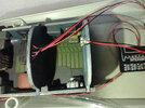
During test fitting, I discovered the fiber optics for the engine nav lights were picking up the glow from the engine lights, so I put a couple of thick coats of black along the length of the fiber.

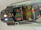
Holes were drilled for the wires to feed into the main body and then all the engine components were fitted into place in one half of each before finally sealing them up for good.


The fibers for the front nav lights were run along and glued to the bottom of the fuelage and glued into the LED adapter. Then the assembled interior was lowered in to place and glued in, making sure the LED wires came up between the inner and outer sides.


The cockpit was assembled in place on the floor of the upper deck & then the whole deck lowered in, taking care not to trap any of the cockpit fibers or wires. With everything in place it was time to connect all the LEDs up for the final time and give everything a test!


Checking all the lights work...


I tried to draw some display info on the tiny little screen with an ultra fine marker pen. They are not great, but at least they don't look blank.
Next job is to connect up all the console fibers into the animated lighting block...
During test fitting, I discovered the fiber optics for the engine nav lights were picking up the glow from the engine lights, so I put a couple of thick coats of black along the length of the fiber.
Holes were drilled for the wires to feed into the main body and then all the engine components were fitted into place in one half of each before finally sealing them up for good.
The fibers for the front nav lights were run along and glued to the bottom of the fuelage and glued into the LED adapter. Then the assembled interior was lowered in to place and glued in, making sure the LED wires came up between the inner and outer sides.
The cockpit was assembled in place on the floor of the upper deck & then the whole deck lowered in, taking care not to trap any of the cockpit fibers or wires. With everything in place it was time to connect all the LEDs up for the final time and give everything a test!
Checking all the lights work...
I tried to draw some display info on the tiny little screen with an ultra fine marker pen. They are not great, but at least they don't look blank.
Next job is to connect up all the console fibers into the animated lighting block...
Last thing to do was install the rear cabin light - this is just a 1206 LED glued to the rear bulkhead so that it's pointing down.


A final test-fit of the top of the fuselage and..... Oh No! Complete disaster!! Some how I have failed to make sure all of the interior was set down into its correct position when I glued it in! I'd dry-run this many times, but this time something went wrong and I didn't notice. The top of the cabin assembly was about 2mm too high and there was a gap all around it with the fuselage in place.
I ended up having to dremel away both the top & side edges, and cut grooves into the underside of the top as deep as I dared in order to get every thing to fit correctly. I made a right mess


That was all a bit demoralising, so I took a break for a while. Finally got back to the last major task for this bit - connecting the fiber optics up to the light module. It was very fiddly trying to get them all distributed across the various effect, so I ended up gluing 6 little bits of styrene tube together and feeding each fiber through one of those.

Once all were done, the ends were cut off to length and each bundle pushed into the respective LED guide hole and fixed in place with some PVA 'tacky' glue.

Amazingly after all this hacking and boggering about, everything thankfully still worked!
Video here
 vimeo.com
A final test-fit of the top of the fuselage and..... Oh No!
Complete disaster!! Some how I have failed to make sure all of the interior was set down into its correct position when I glued it in! I'd dry-run this many times, but this time something went wrong and I didn't notice. The top of the cabin assembly was about 2mm too high and there was a gap all around it with the fuselage in place.I ended up having to dremel away both the top & side edges, and cut grooves into the underside of the top as deep as I dared in order to get every thing to fit correctly. I made a right mess
That was all a bit demoralising, so I took a break for a while. Finally got back to the last major task for this bit - connecting the fiber optics up to the light module. It was very fiddly trying to get them all distributed across the various effect, so I ended up gluing 6 little bits of styrene tube together and feeding each fiber through one of those.
Once all were done, the ends were cut off to length and each bundle pushed into the respective LED guide hole and fixed in place with some PVA 'tacky' glue.
Amazingly after all this hacking and boggering about, everything thankfully still worked!
Video here
Vimeo
vimeo.com
Attachments
modelerdave
Sr Member
The lighting is excellent!
Long time coming, I finally got this finished a couple of weeks ago, albeit in a bit of a rush for a show.
In the end I wasn't very happy with the finish - it was the first time using AK products and I should have experimented a bit first on something disposable. I suffered some major problems with the gloss base coat going down very grainy in places, and with the polished aluminium top coat coming off again with the slightest bit of handling or weathering so I wasn't able to do as much after processing as I intended.
But it will do for now. If I see one cheap I may pick one up for another go at some point.


Video of lights in action here
In the end I wasn't very happy with the finish - it was the first time using AK products and I should have experimented a bit first on something disposable. I suffered some major problems with the gloss base coat going down very grainy in places, and with the polished aluminium top coat coming off again with the slightest bit of handling or weathering so I wasn't able to do as much after processing as I intended.
But it will do for now. If I see one cheap I may pick one up for another go at some point.
Video of lights in action here
Similar threads
- Replies
- 5
- Views
- 1,008
- Replies
- 36
- Views
- 3,418