trekriffic
Sr Member
Well, I guess it's about time I started one of my own 1/350 TOS Enterprise build threads.
First impressions of the kit...
well...
it's like one of my old grilfriends used to say to me years ago..
"God, this thing is BIG!"
Seriously folks, it's the biggest model I've ever worked on, such a sheer joy that it just so happens to be my favorite starship of ALL TIME!
I'm taking all steps necessary to knock my own socks off with this one.
So far I've gotten the upper and lower saucer gridlines filled and sanded using Perfect Plastic Putty. I've sprayed the inside of the two halves with flat black, silver, and flat white in that order. Once I've made a template of where the gridlines go (in case I want to redraw them in pencil) I'll spray with Dupli-color surface filler sandable primer and see if I need to do any more filling. I'm fairly optimistic I got'er smooth as a Vulcan baby's behind though so keep your fingers crossed for me guys.
Here's what I did this past weekend...
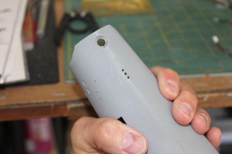
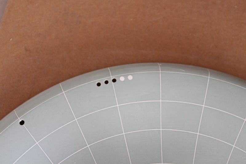
Before I can prime the lower saucer I wanted to take care of that business of the three lower saucer portholes that were molded too far back along the rim on the wrong side of the radial gridline...
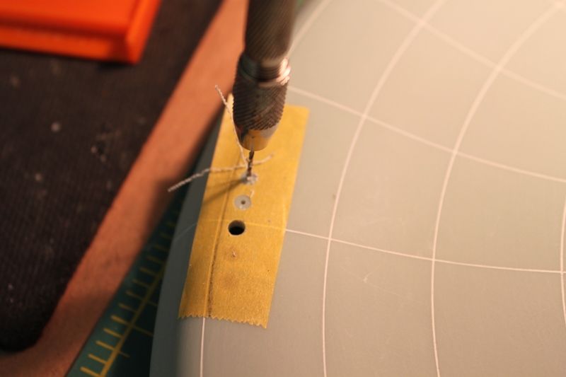
I took some Tamiya tape and poked holes where the current ports were to make a template. Then I placed the template further foward along the arc of the lower rim, overlapping the hole closest o the bow which I kept. So I was only drilling out two new holes on each side:
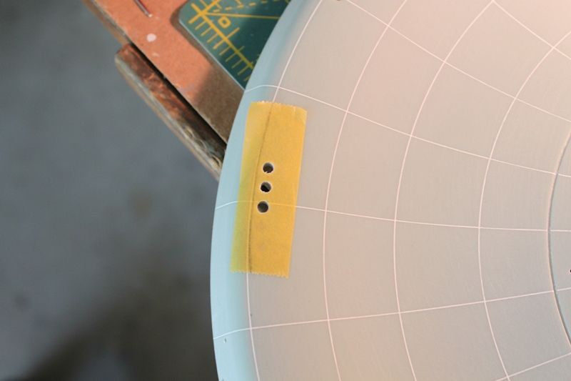
The new holes after drilling and filing:
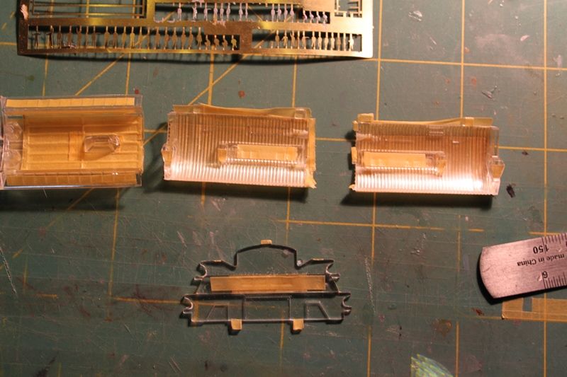
I inserted one of the window inserts into the new hole locations:
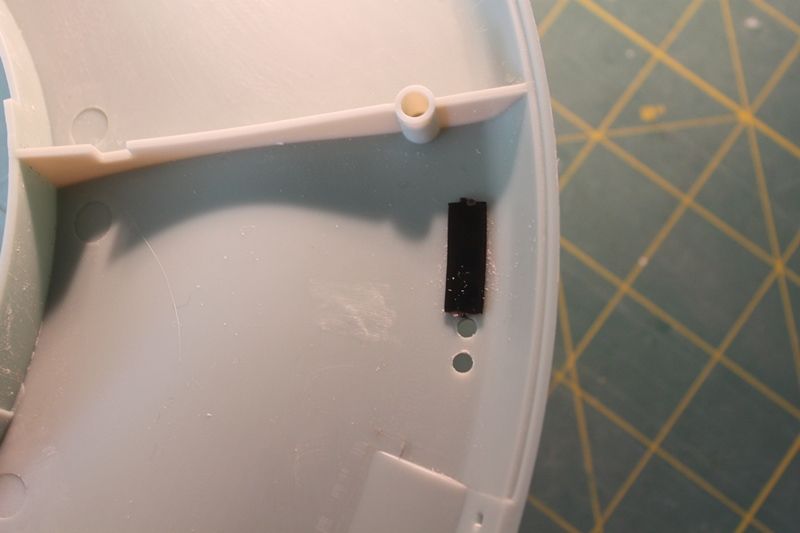
Fit was just right:

The old holes were filled with some clear acrylic rod followed by Perfect Plastic Putty (hereafter referrred to as PPP):
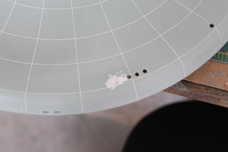
After the PPP dried (about 15 minutes on a nice warm day) I sanded everything nice and smooth:
I did the same thing on the opposite side of the saucer so I saw no need to take any pictures of it.
Next... working on the power jack and plug to the lower secondary hull...
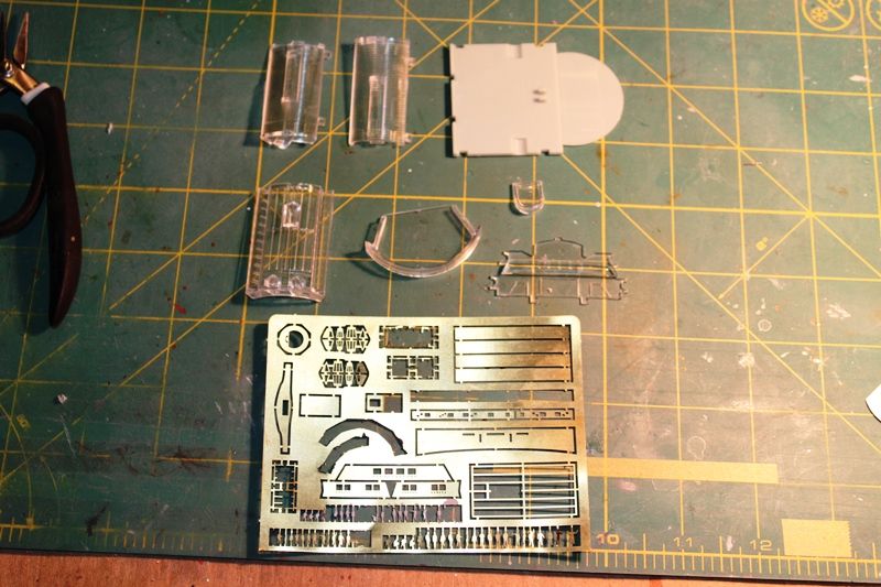
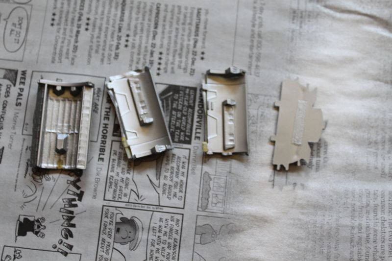
I paid a trip to Fry's Electronics and bought a 4-pin Miini-DIN plug and matching panel jack to use for powering 2 electrical circuits inside the model-one for lights and the other for the bussard motors...
The lower mounting rod support part that inserts into a slot in the lower front of the secondary hull was modified to remove the support tube and insert a larger diameter section of Evergreen tubing. The Evergree tubing inner diameter fit the Mini-DIN plug from the new mounting tube perfectly:

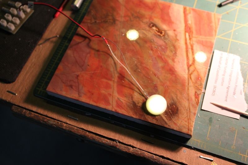
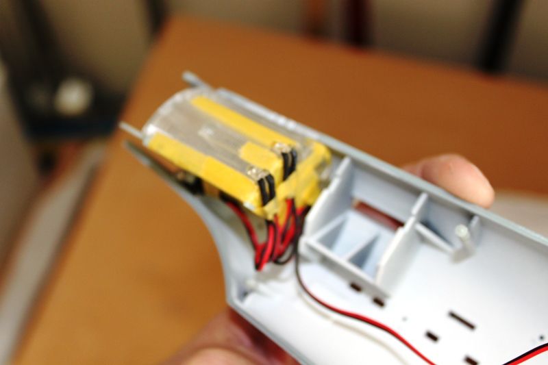
The power plug dry fit onto an aluminum tube:

Inside is a second smaller brass tube glued into the inside of the plug's plastic backshell and the aluminum tube. Four wires for the two circuits willl pass thru the brass tube and down into the aluminum tube which will fit into the base. This should give the support tube much more strength and rigidity than it would have otherwise.
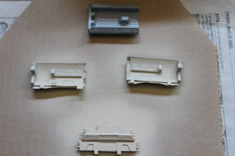
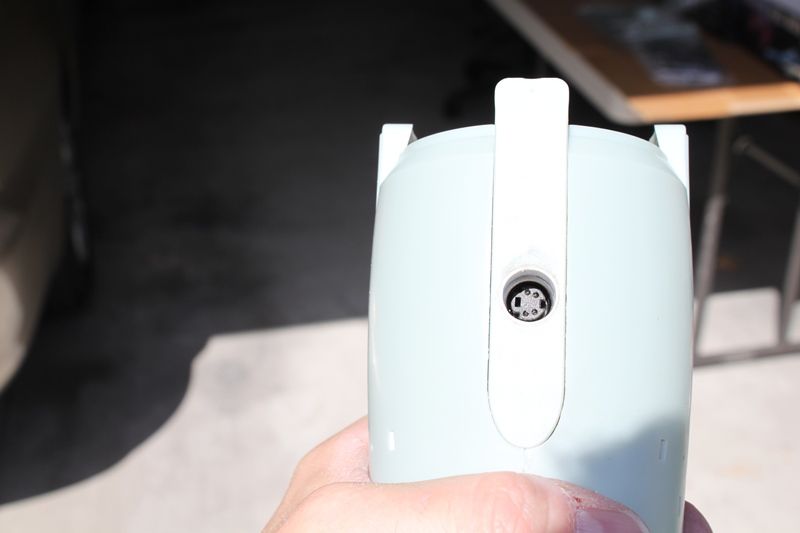
The lower secondary hull mounting point was modified to accomodate the new panel jack. I was amazed at how well it fit. All I did was carve out some slots in the plastic support framing so the metal panel jack base would fit:
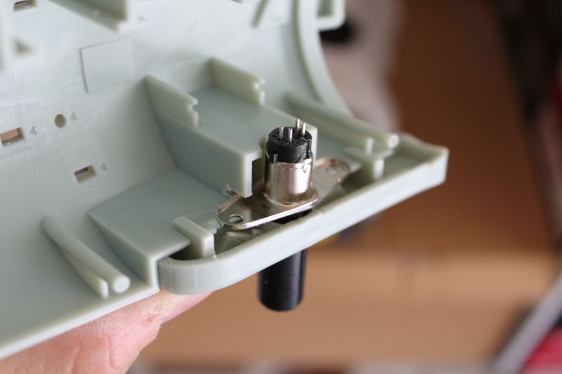
The panel jack had pins that stuck up higher than was planned when the kit was designed which meant I had to create new brackets to provided clearance for the PC lighting board to slide into place:
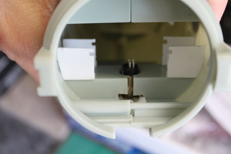
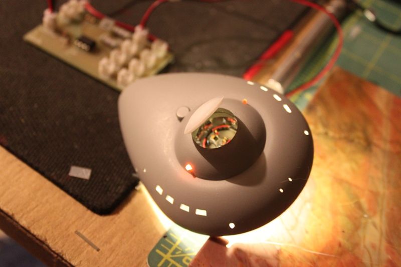
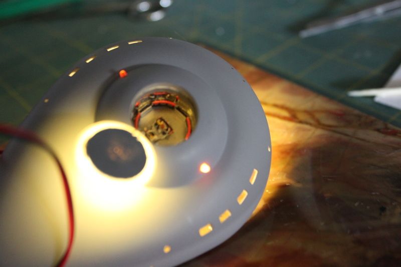
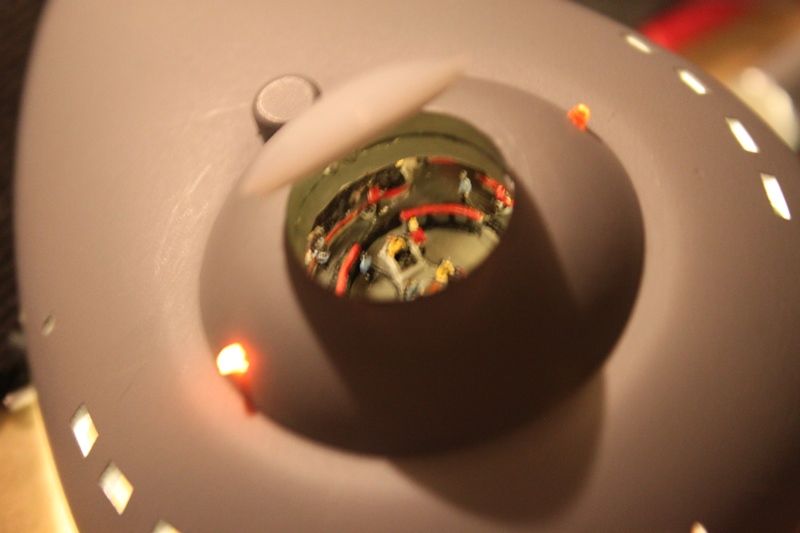
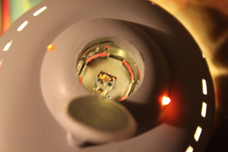
Looking thru the mounting tube in the underside of the ship at the 4-pin Mini-DIN jack:
Dry fit with the mounting tube plugged into the secondary hull. Once the ship is assembled and the mounting points have been glued in and reiniforced with epoxy putty for stiffening it should balance front to back just fine:

Next up... those bussards... they task me... they task me...
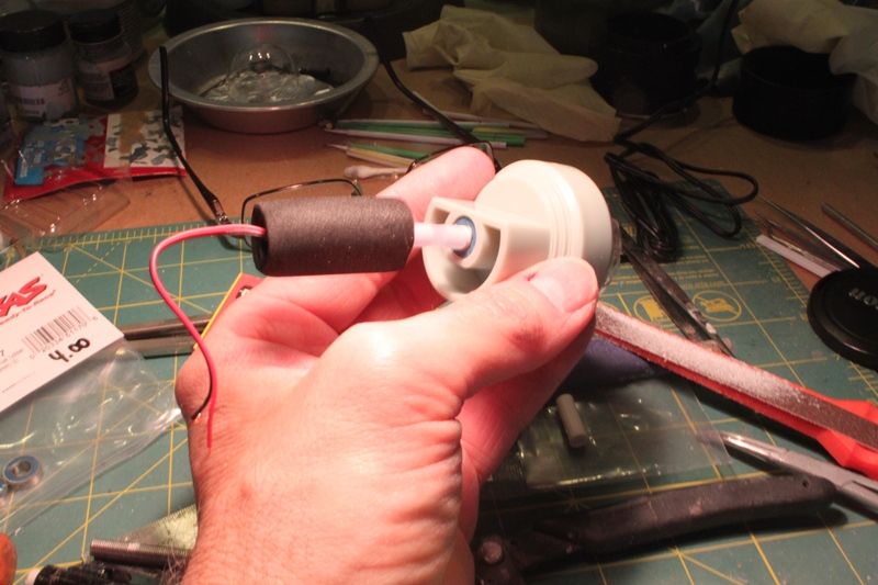
Previously, over in the Tips and Trcks thread over on HobbyTalk (please don't hit me guys for mentioning the dreaded HT here), I'd posted about my version of the system JHauser came up with for quieting the bussard motors using brass axles inside of ball bearings mounted inside the tunnel of part 42 and isolating the motors from the plastic of the nacelles using foam padding to reduce motor vibration and noise. Work progressed on this as I took some time over the weekend to tweak a few things with the bearings inside the tunnel. One thing was to cut a small piece of Evergreen tubing and insert it between the bearings so they would maintain their positions at the front and back of the tunnel. Even though they fit like a glove, the process of inserting the drive axles tended to force them forward or backward so the spacer would take care of that issue. I took a piece of plastic tubing a little larger than the inside diameter of the tunnel and after cutting it to the exact distance between the two bearings I cut out a small longitudinal section of the tubing, test fitting until it slid inside the tunnel under spring tension:
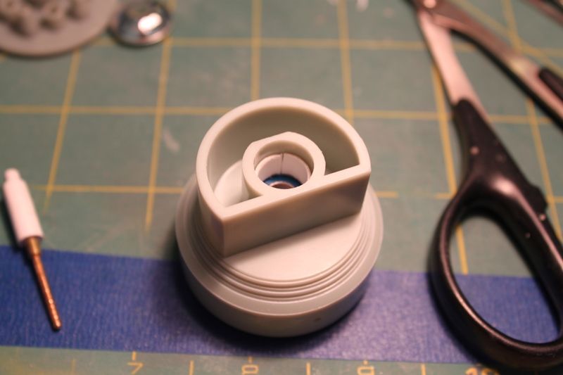
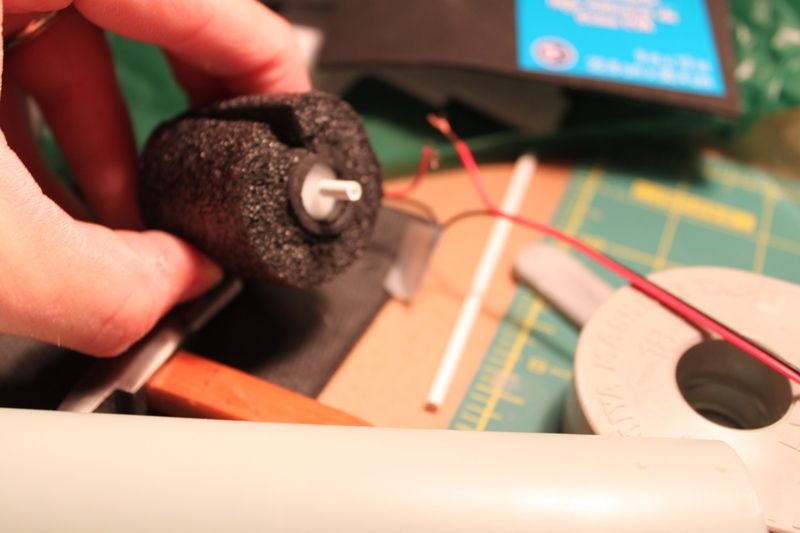
The rear bearing was then inserted into the tunnel:
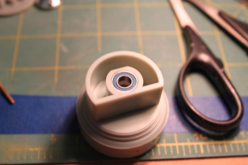
Subsequently the bearings were sealed into the tunnel in part 42 with a homemade styrene "washer" glued on the back side of the part so the bearing wouldn't pop out of the tunnel when inserting the spinner drive axle. Sorry, no photo of this, so you'll have to use your own imagination!
Next I had a brilliant idea; or, what might be a brilliant idea if it works...
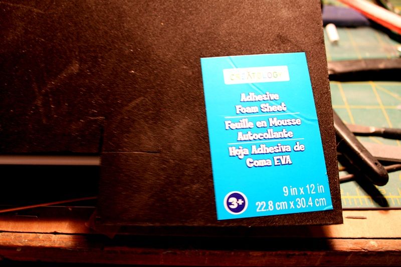
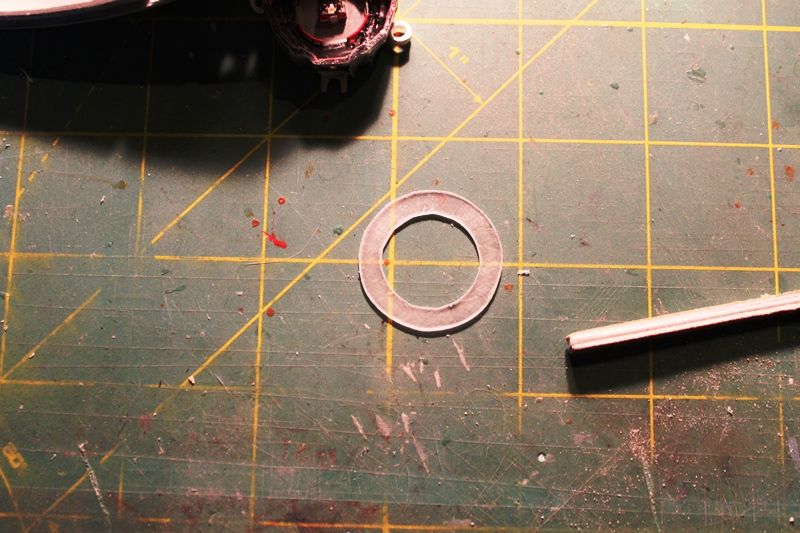
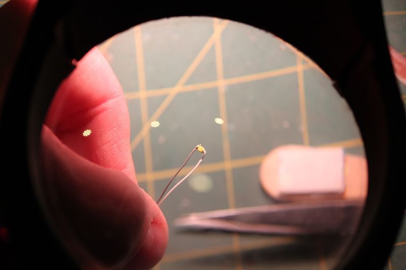
I'm going to redo the LEDs on the round lighting kit bussard circuit board to lengthen their legs so they will fit up and thru the "towers" in part 142 and inside of the colored plastic teardrop shaped inserts provided with the lighting kit which I will be hollowing out. This will involve either snipping or desoldering the legs of the existing PC board LEDs and replacing them with lights I bought online from Lighthouse LEDs. The new lights are ultrabright-wide angle-diffused LEDs in various colors-they even had pink! So I should get a LOT more light inside the domes than otherwise. Another thing I wanted to do was create a way to bounce the light around under the spinning fan dome and onto the inside surface of the outer bussard dome which is where I got this next idea using faceted chrome plated plastic buttons I'd bought at the craft store for use on another project:
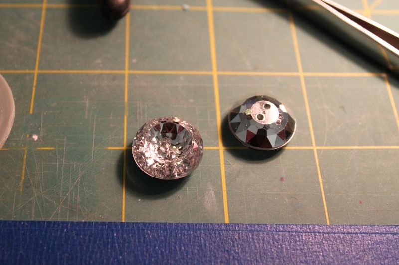
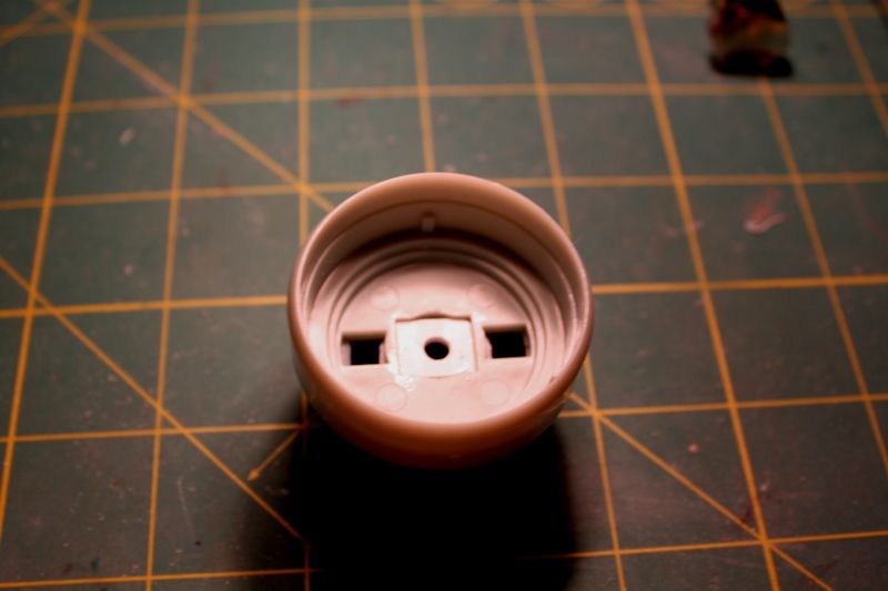
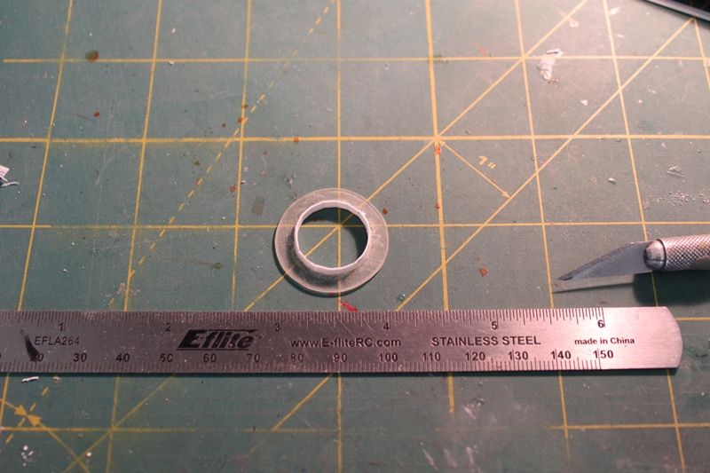
The buttons fit perfectly in the center of part 142 between the light towers:
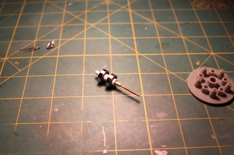
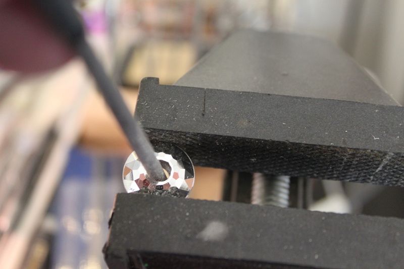
So... I drilled, routed, and filed a hole in the center of each button:
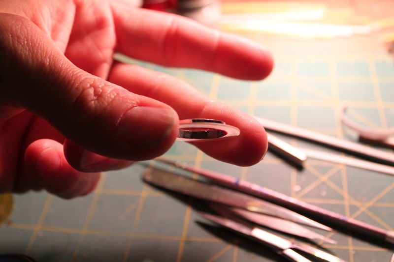
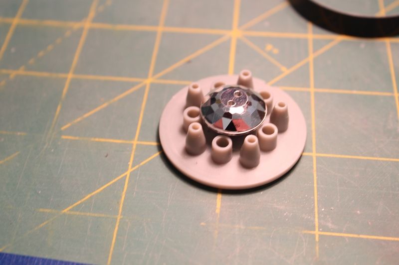
It press fit onto the spinner shaft easily:
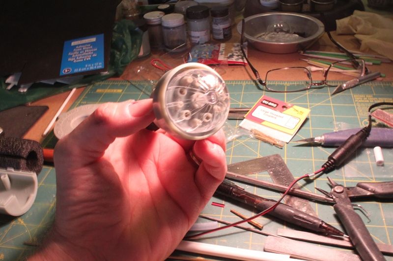
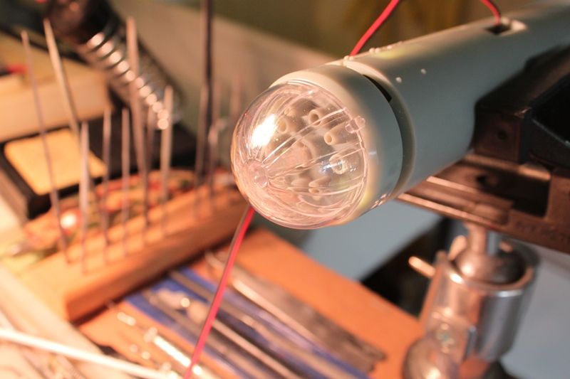
Test fitting with the mirror button in position under the spinner and LEDs:
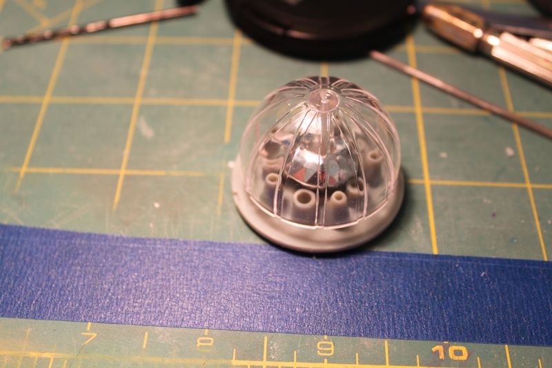
I'm hoping once I have the lights modified and lit, and the spinner going, the facets will bounce light from the LEDs above them as the spinner rotates. That's the plan anyway. You know, based on whether I place the button right side up (convex) or upside down (concave) on the spinner shaft I may get a different light effect. This may be one of my best ideas ever... or not... :-\
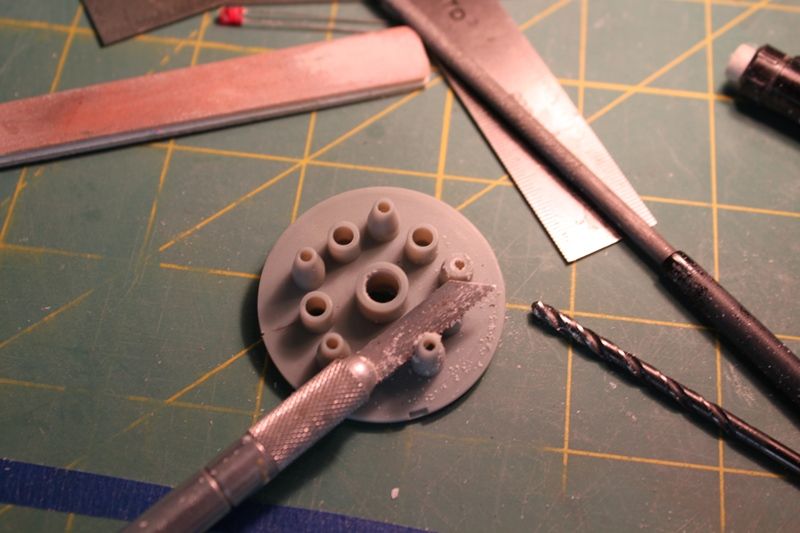
The last thing I did this weekend was cut off the tops of the taller LED towers on part 142 and widen the openings so the 3mm LEDs can pass completely thru:
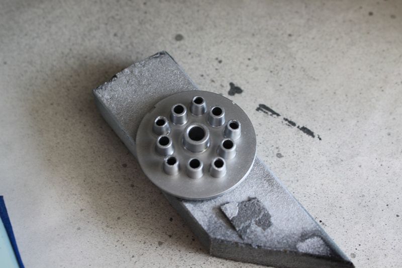
Then I sprayed the part with Testors gloss silver:
I also bought a sheet of color changing foil paper they sell at Michaels craftstore. It has little stars and comets on a dark blue background that shift from gold to blue to red as you tilt the paper in the light. Man is this stuff reflective! I plan on making discs with holes cut out to fit the spacing of the light towers so I can attach the paper to the face of part 142 under the LEDs. It might be overkill but every little bit helps if it gets me an effect close to what we saw on TV back in the day! Dontcha just love experimentation! Man that's the stuff right there!
Thanks for reading along. More to come soon!
First impressions of the kit...
well...
it's like one of my old grilfriends used to say to me years ago..
"God, this thing is BIG!"
Seriously folks, it's the biggest model I've ever worked on, such a sheer joy that it just so happens to be my favorite starship of ALL TIME!
I'm taking all steps necessary to knock my own socks off with this one.
So far I've gotten the upper and lower saucer gridlines filled and sanded using Perfect Plastic Putty. I've sprayed the inside of the two halves with flat black, silver, and flat white in that order. Once I've made a template of where the gridlines go (in case I want to redraw them in pencil) I'll spray with Dupli-color surface filler sandable primer and see if I need to do any more filling. I'm fairly optimistic I got'er smooth as a Vulcan baby's behind though so keep your fingers crossed for me guys.
Here's what I did this past weekend...
Before I can prime the lower saucer I wanted to take care of that business of the three lower saucer portholes that were molded too far back along the rim on the wrong side of the radial gridline...
I took some Tamiya tape and poked holes where the current ports were to make a template. Then I placed the template further foward along the arc of the lower rim, overlapping the hole closest o the bow which I kept. So I was only drilling out two new holes on each side:

The new holes after drilling and filing:

I inserted one of the window inserts into the new hole locations:

Fit was just right:

The old holes were filled with some clear acrylic rod followed by Perfect Plastic Putty (hereafter referrred to as PPP):

After the PPP dried (about 15 minutes on a nice warm day) I sanded everything nice and smooth:

I did the same thing on the opposite side of the saucer so I saw no need to take any pictures of it.
Next... working on the power jack and plug to the lower secondary hull...
I paid a trip to Fry's Electronics and bought a 4-pin Miini-DIN plug and matching panel jack to use for powering 2 electrical circuits inside the model-one for lights and the other for the bussard motors...
The lower mounting rod support part that inserts into a slot in the lower front of the secondary hull was modified to remove the support tube and insert a larger diameter section of Evergreen tubing. The Evergree tubing inner diameter fit the Mini-DIN plug from the new mounting tube perfectly:

The power plug dry fit onto an aluminum tube:

Inside is a second smaller brass tube glued into the inside of the plug's plastic backshell and the aluminum tube. Four wires for the two circuits willl pass thru the brass tube and down into the aluminum tube which will fit into the base. This should give the support tube much more strength and rigidity than it would have otherwise.
The lower secondary hull mounting point was modified to accomodate the new panel jack. I was amazed at how well it fit. All I did was carve out some slots in the plastic support framing so the metal panel jack base would fit:

The panel jack had pins that stuck up higher than was planned when the kit was designed which meant I had to create new brackets to provided clearance for the PC lighting board to slide into place:

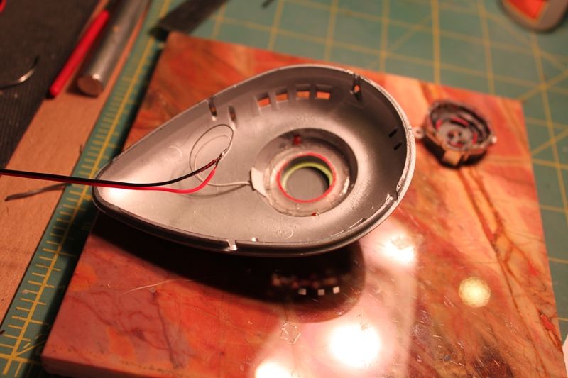
Looking thru the mounting tube in the underside of the ship at the 4-pin Mini-DIN jack:

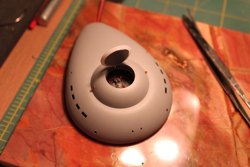
Dry fit with the mounting tube plugged into the secondary hull. Once the ship is assembled and the mounting points have been glued in and reiniforced with epoxy putty for stiffening it should balance front to back just fine:

Next up... those bussards... they task me... they task me...
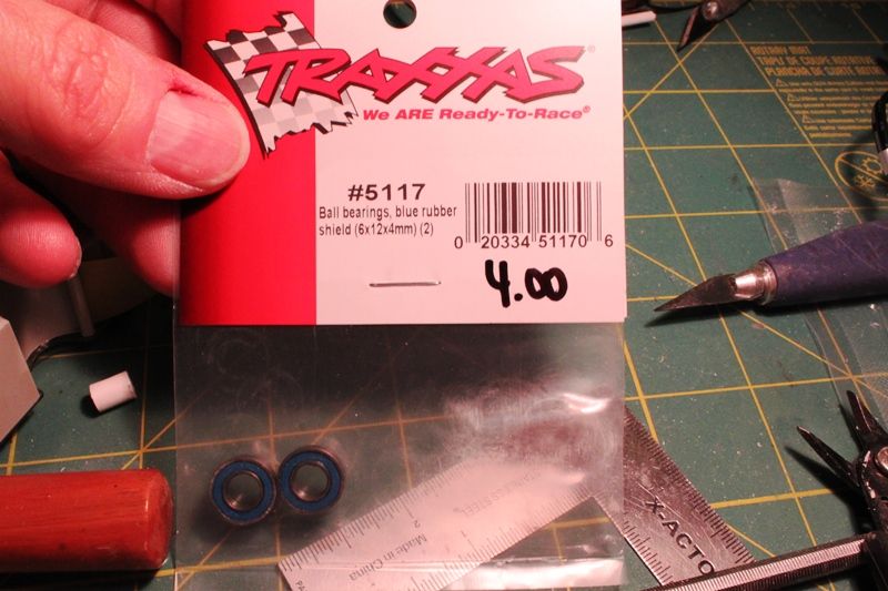
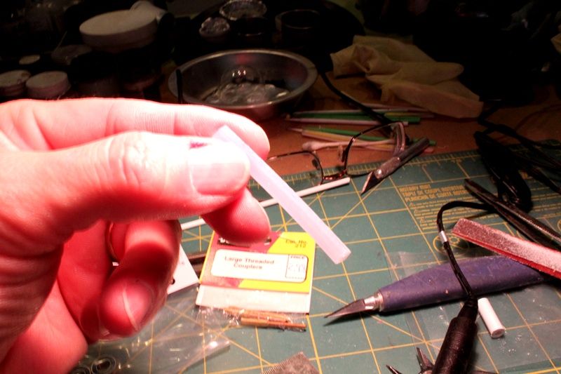
Previously, over in the Tips and Trcks thread over on HobbyTalk (please don't hit me guys for mentioning the dreaded HT here), I'd posted about my version of the system JHauser came up with for quieting the bussard motors using brass axles inside of ball bearings mounted inside the tunnel of part 42 and isolating the motors from the plastic of the nacelles using foam padding to reduce motor vibration and noise. Work progressed on this as I took some time over the weekend to tweak a few things with the bearings inside the tunnel. One thing was to cut a small piece of Evergreen tubing and insert it between the bearings so they would maintain their positions at the front and back of the tunnel. Even though they fit like a glove, the process of inserting the drive axles tended to force them forward or backward so the spacer would take care of that issue. I took a piece of plastic tubing a little larger than the inside diameter of the tunnel and after cutting it to the exact distance between the two bearings I cut out a small longitudinal section of the tubing, test fitting until it slid inside the tunnel under spring tension:

The rear bearing was then inserted into the tunnel:

Subsequently the bearings were sealed into the tunnel in part 42 with a homemade styrene "washer" glued on the back side of the part so the bearing wouldn't pop out of the tunnel when inserting the spinner drive axle. Sorry, no photo of this, so you'll have to use your own imagination!
Next I had a brilliant idea; or, what might be a brilliant idea if it works...
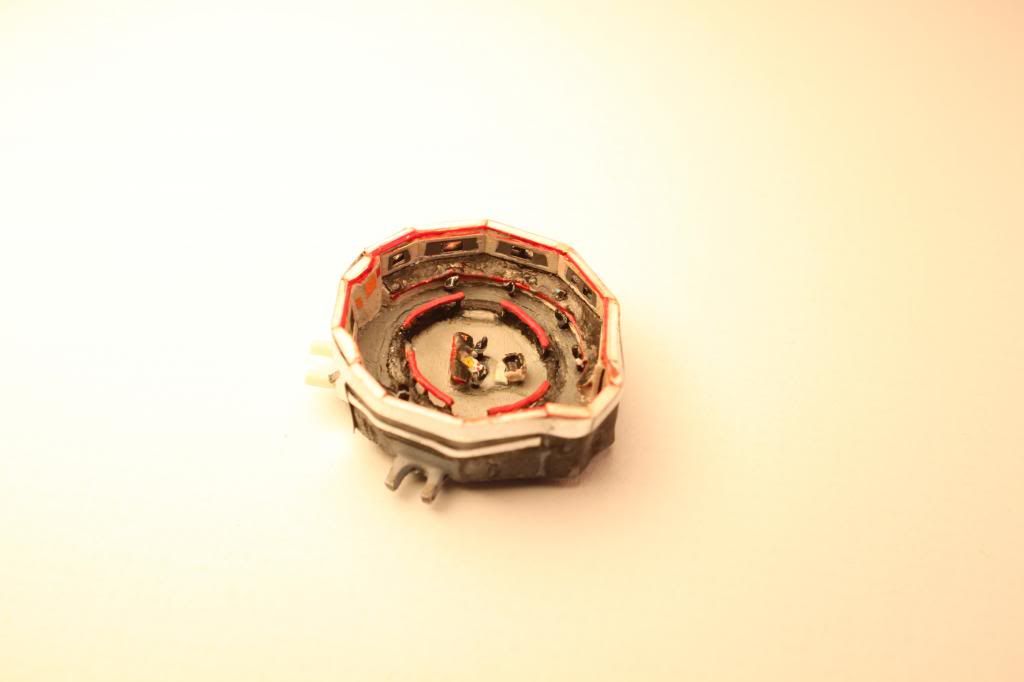
I'm going to redo the LEDs on the round lighting kit bussard circuit board to lengthen their legs so they will fit up and thru the "towers" in part 142 and inside of the colored plastic teardrop shaped inserts provided with the lighting kit which I will be hollowing out. This will involve either snipping or desoldering the legs of the existing PC board LEDs and replacing them with lights I bought online from Lighthouse LEDs. The new lights are ultrabright-wide angle-diffused LEDs in various colors-they even had pink! So I should get a LOT more light inside the domes than otherwise. Another thing I wanted to do was create a way to bounce the light around under the spinning fan dome and onto the inside surface of the outer bussard dome which is where I got this next idea using faceted chrome plated plastic buttons I'd bought at the craft store for use on another project:

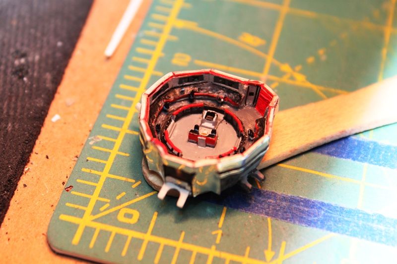
The buttons fit perfectly in the center of part 142 between the light towers:

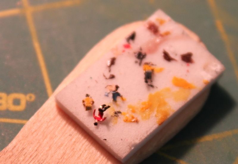
So... I drilled, routed, and filed a hole in the center of each button:

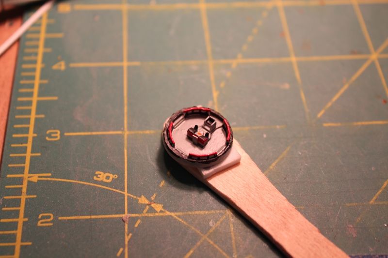
It press fit onto the spinner shaft easily:

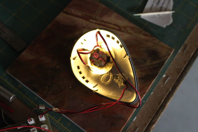
Test fitting with the mirror button in position under the spinner and LEDs:

I'm hoping once I have the lights modified and lit, and the spinner going, the facets will bounce light from the LEDs above them as the spinner rotates. That's the plan anyway. You know, based on whether I place the button right side up (convex) or upside down (concave) on the spinner shaft I may get a different light effect. This may be one of my best ideas ever... or not... :-\
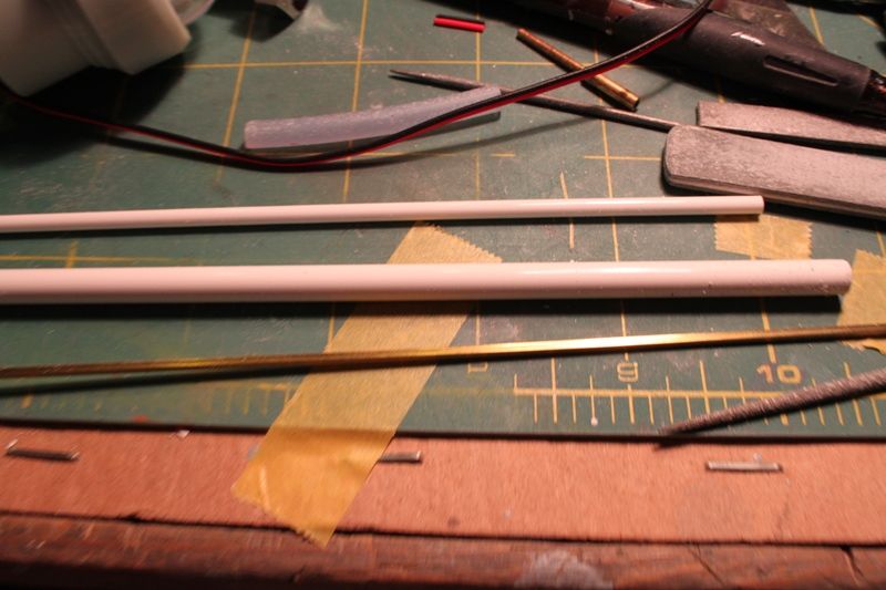
The last thing I did this weekend was cut off the tops of the taller LED towers on part 142 and widen the openings so the 3mm LEDs can pass completely thru:

Then I sprayed the part with Testors gloss silver:

I also bought a sheet of color changing foil paper they sell at Michaels craftstore. It has little stars and comets on a dark blue background that shift from gold to blue to red as you tilt the paper in the light. Man is this stuff reflective! I plan on making discs with holes cut out to fit the spacing of the light towers so I can attach the paper to the face of part 142 under the LEDs. It might be overkill but every little bit helps if it gets me an effect close to what we saw on TV back in the day! Dontcha just love experimentation! Man that's the stuff right there!
Thanks for reading along. More to come soon!
Last edited: