You are using an out of date browser. It may not display this or other websites correctly.
You should upgrade or use an alternative browser.
You should upgrade or use an alternative browser.
Mutara Nebula DeBoers E and R Build
- Thread starter jwood314
- Start date
Holy cow, that's a crazy amount of switches. 32 hull lights! You're awesomely insane.I know I am slow on posting, but the working I am doing is really slow, and not very photographic. Pre-wiring 100 switches is not terribly exciting, nor is checking that they all work after the solder work. One of them failed, so super glad I tested them all! Also, soldering all of the circuit boards up by hand takes some time.
whiskeyrat
New Member
Hoo boy... I've got my DeBoer Enterprise sitting waiting for me, and now the bar's been set way higher! fantastic work on both ships!
Agreed!! IMO, this is truly an epic lighting system.Hoo boy... I've got my DeBoer Enterprise sitting waiting for me, and now the bar's been set way higher! fantastic work on both ships!
I'm really looking forward to seeing what each of the 32 individual light switches actually turns on. I've got a stand I'm working on for a bud, this is a true inspiration. I can't say I'll ever get to where OP is, but I will try to get 1/2 way.
I want to thank everyone for the massively kind words! Makes getting motivated to burn brain power easier!
My philosophy on life is pretty much go big or go home!
More work complete, panels glued in and stuff getting wired up.
I have also decided to redo all of the control boards with the new control circuitry, which will massively clean up the inside of the case, and also make the electronics and base have much better reliability. I have 4 of the boards done, and I am working on the largest and most complex one now. Hopefully, in a few days get them done and into manufacturing. I will post what the new cost is to make these boards. A couple more pics.
modelerdave
Sr Member
You know, all of the hex nuts around the toggle switches not being oriented in the same direction just ruins everything. ")
Kidding! My god, I think the base might be more epic than the ship itself!
Kidding! My god, I think the base might be more epic than the ship itself!
I agree about the hex nuts, I tried, but I was really concerned with scratching up the plexiYou know, all of the hex nuts around the toggle switches not being oriented in the same direction just ruins everything.
Kidding! My god, I think the base might be more epic than the ship itself!
Also, cheap nuts.I got the boards done and the are being manufactured. I figure I through some pics up of the boards. Parts are all ordered and hopefully in about 2 weeks I will get to start putting these together, testing them, installing them and getting the base wired up and ready for the model. Just need the plexi tops, then this 7-year effort will be complete and up for sale. Will take some pics of the completed boards.
Cheers,
James
Attachments
The override is the button on the left, underneath the DIP switch above the illuminated pushbutton switch....
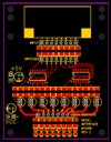
The boards showed up, waiting on the parts order, but I had enough parts to build the little DIP switch mounting board that goes into the back
acrylic panel. This little board keeps me from having to solder 100ish wires and instead just use jumper-terminated wire. Super excited!


The boards showed up, waiting on the parts order, but I had enough parts to build the little DIP switch mounting board that goes into the back
acrylic panel. This little board keeps me from having to solder 100ish wires and instead just use jumper-terminated wire. Super excited!
All of the little boards have been built and tested and programmed. I have verified all of the functionality of the big board, but had to order some parts to fix an issue Getting closer though to have all of the electronics working, installed into the base, and 97% off the switches wired in and working. Down to the top panels for the base and clean up. I have noticed a few nitnoid things I need to correct on the Reliant herself.
Here is a gratuitous electronic shot.
Cheers,
James

Getting closer though to have all of the electronics working, installed into the base, and 97% off the switches wired in and working. Down to the top panels for the base and clean up. I have noticed a few nitnoid things I need to correct on the Reliant herself.Here is a gratuitous electronic shot.
Cheers,
James
Update #120?
A ton of work on the code and electronics to run the ship. First three shots are of the base with much of the wiring and boards installed. I have to redo some of the logic on the main board and parts are in the mail. So I couldn’t wire everything in, but did a lot of the wiring. All of the periphery boards work and all of their functionality is there. The code is only written to test everything the board is supposed to do, will have to write final code later.
I learned a CAD program, TInkerCAD, so I could design the stack up to hold the attitude boards, light board, servo, and eventually the custom acrylic part. I will have 3 of these stack ups when complete. I am still fixing some minor issues on a few of the parts. There are 5 custom parts needed for each attitude stack.
Everything is coming along really well. I have not started on the user guide, but there are so many options and controls and setting that a person can set on the model, need some sort of documentation to let people know how to run the Reliant!
I have about a day of minor minor touch ups left on the actual model itself, but I won’t do those until she is ready to mount into the base. I am hopeful that will be in about a month or so. Then, get everything wired up, software finished, user book done and then sell her. 7 plus years to get here, lol.
Cheers,
James
I love cable management, I think it is a sickness I have.....
Those are not connectors, that is the backside of the single pole single throw switch. Every connection is soldered and has heatshrink applied. That it for those.
The dip switches control various stuff. For the interior of the shuttle bays, might be blinking LED speed on the shuttles, other behavior inside the shuttle bay, for the attitude designators I need a way to put them into assembly mode, basically I need to force the servos to go to 90 degrees so I can install the top acrylic piece. The dip switches will also control aspects of the RCS thrusters, I have 2 twinkle modes, a solid mode - basically each RCS thruster just turns on or off and other is an all on or off setting. There are some other functions I am thinking of, and also, there are some spare switches there. I want as much control as possible over the lighting in the model. 99% of the models I see are usually 1 or 2 switches and then everything is on/blinking, I built the model and electronics to have a crap load of control. Each lighting section within the model has its own power switch, so 32 zones in the model, that are controlled either through the front panel switch or software if you want. Etc. Also, having all of those light zones allows for some cool effects when in battle mode! Well, in my head they are cool effects, but hopefully I can get that vision into the code.
Some more progress. I have 2 3D parts left to print. I am waiting on the last few remaining logic chips, which is pissing me off, over 3 weeks to get here. Once those are here, I can finish up the base electronics. Then I need the last acrylic pieces then final assembly!
Cheers,
James
Woohoo, the parts came in. I finished the main board. All functionality on all of the boards works. I have 99% of the front and rear panel now hooked into the boards. I worked on cleaning up the cables, mainly just getting the neater. I have a bug on the torpedo board, working with Stan to get that corrected. I am 3D printing some boxes that will hold the USB port for the main boar, that Arduino Mega is underneath the main board, so I need a cable extender. Need to mount a few more things, but about to be waiting on the top acrylic panels, so I can set the attitude assemblies into the bottom and wire in the model. So close!
Cheers,
James

Cheers,
James
Looking great! It's a shame the panel is split down the center.I got the panels in! Unfortunately, I am traveling for the rest of March and won't be able tow work on her until April. Not sure if I can get her done before I have to move.
View attachment 1796128
Agreed, but I couldn't come up with a way to do what needs to happen underneath the panel and then integrate the model into the base. Hopefully, that will make more sense over the next few months as I get the base built out and working.Looking great! It's a shame the panel is split down the center.
Cheers,
James
Millenniumf
Sr Member
Man, when this is completed it'll be one of the best Star Trek display pieces ever made!
Took about 6 months but we got our house moved from Germany to Texas. We moved into our temporary home for the next year, and I have the model back up and I am working on her again. I have done a ton of work, but it is all boring. I had to redo the shields board, I couldn't come up with a way to build it and integrate it into the base, so a new board is being made and then on the way. When the board gets here will take a few pics. I am working on the button lights, which requires a large amouint of printing. My first prototype for the buttons also couldn't be built, I detect a theme here. The model itseld has some minor touch ups required, but I don't have an air brush station solution yet, so that is on hold, so full steam on the base. I have a list of items that need finishing and working through it. Maybe a few more months, depends on the job situation. I am just glad to be back up and running on the model. One big benefit of all this work on the Reliant base, it all translates over to the Enterprise base almost 100%, there are a few differences in the code but none of the hardware will change. I do look forward to being complete with both of these models. I have others I want to work on!
Cheers,
James

Cheers,
James
Similar threads
- Replies
- 11
- Views
- 1,080