</SPAN><TABLE BORDER=0 ALIGN=CENTER WIDTH=85%><TR><TD CLASS=$row_color>
Oohyeah KL wrote:<HR></TD></TR><TR><TD CLASS=$row_color>
<TABLE BORDER=0 ALIGN=CENTER WIDTH=85%><TR><TD CLASS=$row_color>
Brevin Din-Shay wrote:<HR></TD></TR><TR><TD CLASS=$row_color>
My question is simply this: What EXACTLY have we pinpointed in this thread as "certainties?" </TD></TR><TR><TD><HR></TD></TR></TABLE>
OK, let me take an initial stab, at least so that I know whether I'm getting it right or not:
- bottom end is not made of wood nor cheese (sorry, couldn't resist...
)
ok, seriously... first, the non-contentious (I think):
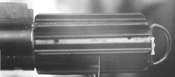
- bottom half surface texture appears very different to top half, but most likely came from a Luke ESB
- 3 holes show between the grips (2 at bottom end, one on top)
- There's a metal disc thingy on the end, which curves 'concavely' inwards under pressure of the D-ring assembly
- There's a little hole further down the tube from the door latch (thanks, Kenny)
- The control box cylindrical things are most likely screws, with the notches at the top covered by paint so much so that they are hardly visible anymore
The contentious:
- Unclear whether bottom end is a Graflex base or not. Could be Graflex but covered with adhesive residue, or a custom base.
- Top hole between grip may or may not be a grip hole
- metal disc thingy could be washer or just a sheet metal disc
- metal disc thingy is brass? Rusted metal?
- metal disc thingy was painted gray? or had muck over it? or was sanded to show the striations?
- WTF is that notch/notches exposed under the control box? could be the graflex L-notch?
- AND LOTS, LOTS MORE...
</TD></TR><TR><TD><HR></TD></TR></TABLE><SPAN CLASS=$row_color>
Here's some more to add to the list...
- Activation Box has been reported to be the housing from a momentary action electrical switch, but
Darth Saber found a similar looking car circuit breaker (YJ-9340L).
- D-Ring is rusty with only a few spots of chrome remaining.
- Linhof bracket is mounted with rivets (they have 1/4" heads and appear to be aluminum).
- Ball catch is hollow, made from nickel or chrome plated pressed steel.
- Only one synchronizer port pin remains in the Graflex shell (it's in the lower hole of the socket that is left of the recharge port/tire valve).
- Recharge port is chrome/nickel plated brass and has a thread down inside the inner hole - it's likely to be a universal clamp-in tire valve).
- Grips are mounted with either hot glue or a clear epoxy resin.
- Graflex head shell seems to have been cut in half across the test bulb socket - something inside the saber (maybe white or grey PVC tubing) butts up against the remaining portion of the head shell.
- Flat-head countersunk socket bolts are 1/2" in diameter.
Steve