Well....I knew I had to make some of these at one point or another. It was really just a matter of having the time. I finished exams last week and have been diving back into projects headfirst.
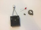
I started by sketching up a rough design of the prop in Mando's hand as well as other shots with the multiple fobs on the table in the cantina. I also made a rough prototype for size reference out of foamboard, Cardboard, some foam tape, and some headphone wire pictured below. I used reference from the show as well as from parts known to have been used to make the original props(train graphite motor brushes) Here


*I want to make this clear: This is not an exact replica of any particular prop from the show. As far as I've seen there are at least 3 main variants of the prop itself. This is a bit of a hodgepodge of all the variants that I've picked certain characteristics from.* It will still make a nice addition to a future Baby Yoda/The Child/ Grogu display. Also, I totally took this first picture from another thread here for the tracking fob Here


The height of the side rails on the front face as well as the Graflex beer tab looking part which surrounds the red light vary between the different versions.
What I planned do do is have a small Cast resin box with a hollow, open back which will allow for the electronics to be seated in the box. Then, on my version, a bend piece of steel sheet metal will 'clasp' around the main body as well as cover the hollow cavity with electronics.. The sections folded over on the front face will become the front rails.
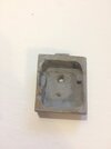
Although I would have preferred to have modelled and 3-D printed the main body, I took it as a personal challenge to make it completely by hand without any machine assistance. I do plan to someday machine one out of aluminum to give it some realistic heft. Below is the final master I made with a washer I modified, a small piece of craft foam hand cut to shape, along with some small supports on the inside for the electronics and antenna later.

in the bottom right you can just see some of the various parts I was attempting to use as opposed to modifying everything. Don't mind the slight clutter..I had just finished my exams XD.
More to come!
-Farrell
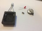
I started by sketching up a rough design of the prop in Mando's hand as well as other shots with the multiple fobs on the table in the cantina. I also made a rough prototype for size reference out of foamboard, Cardboard, some foam tape, and some headphone wire pictured below. I used reference from the show as well as from parts known to have been used to make the original props(train graphite motor brushes) Here
*I want to make this clear: This is not an exact replica of any particular prop from the show. As far as I've seen there are at least 3 main variants of the prop itself. This is a bit of a hodgepodge of all the variants that I've picked certain characteristics from.* It will still make a nice addition to a future Baby Yoda/The Child/ Grogu display. Also, I totally took this first picture from another thread here for the tracking fob Here
The height of the side rails on the front face as well as the Graflex beer tab looking part which surrounds the red light vary between the different versions.
What I planned do do is have a small Cast resin box with a hollow, open back which will allow for the electronics to be seated in the box. Then, on my version, a bend piece of steel sheet metal will 'clasp' around the main body as well as cover the hollow cavity with electronics.. The sections folded over on the front face will become the front rails.
Although I would have preferred to have modelled and 3-D printed the main body, I took it as a personal challenge to make it completely by hand without any machine assistance. I do plan to someday machine one out of aluminum to give it some realistic heft. Below is the final master I made with a washer I modified, a small piece of craft foam hand cut to shape, along with some small supports on the inside for the electronics and antenna later.
in the bottom right you can just see some of the various parts I was attempting to use as opposed to modifying everything. Don't mind the slight clutter..I had just finished my exams XD.
More to come!
-Farrell
") )
)