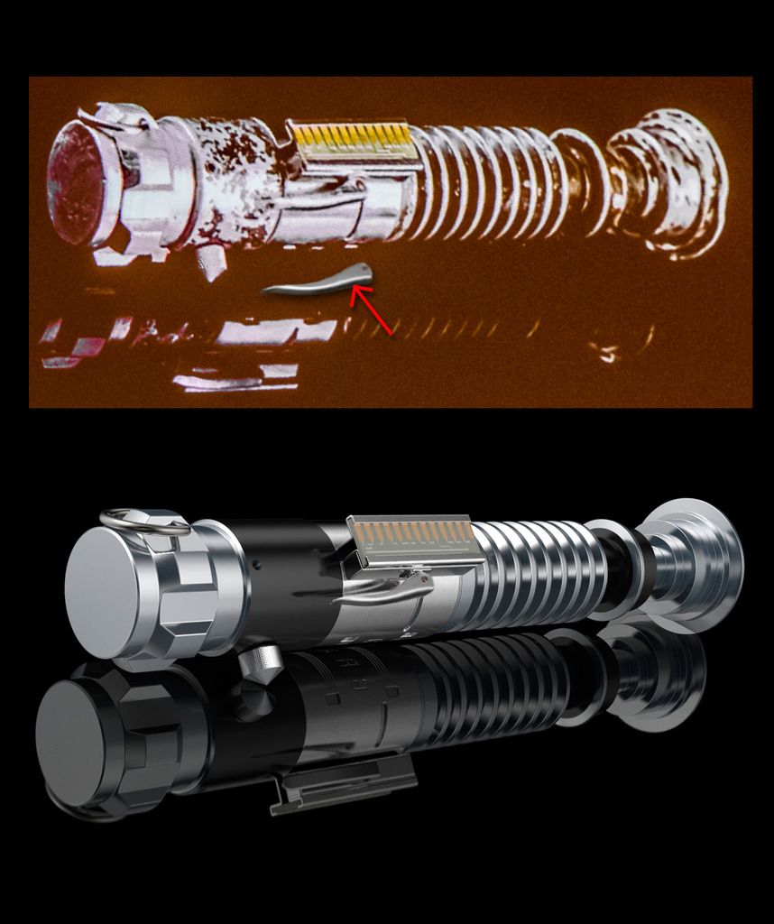
Luke ROTJ V2 lightsaber

Sorry if this is a complete noob question but what's up with thickness of the neck area? These look way off to me.
v2compair-4.jpg
The upper neck (towards the emitter) appears to be the same thickness or even a tad thicker than the lower neck area.
Untitled.png

but in the model it's clearly quite a bit thinner.
 
Last edited:
So ... I took one of Roy's lever of his picture in PS ... and toggled with it myself ... since I was still not completely satisfied ... although I know it's still a render and early stages but one particular curve has been overlooked (see red arrow) :


. . . also I strongly feel there should be more of a curve over 2/3rd of the body, which gives the appearance of being round instead of straight from top till the end. Which by the way you can see happening now when I overlay 'my' lever over Roy's render of the complete saber. Thoughts or suggestions anyone?

Chaim
 
I'd say that's a good tweak. I wish I had the computer skills to show what I'm seeing. I see the lever as thicker on the fat part, and less curved on the fat part on the side toward the circuit card. I see the tip "upturn" as being shorter and steeper. But...since I can't render or even use MS Paint particularly well, my observations are pretty much unhelpful, since I can't show anyone what I'm trying to say :(
 
I remember hearing years ago that the circuit board in the clamp came from either a Comodore 64 or 128 computer. I google searched pics of the motherboards and none of the edge connectors look like the one on the prop.
 
I usually exaggerate to make my point come across ... but yeah cayman shen since we are looking at already distorted pictures from SWC and working from there either in 3D or PS ... it's still quite difficult to capture what our eyes seem to see on the screen and translate that to a real 3D object in true space :)

Chaim
 
I remember hearing years ago that the circuit board in the clamp came from either a Comodore 64 or 128 computer. I google searched pics of the motherboards and none of the edge connectors look like the one on the prop.

From my "physics lab junk" source I also got some commodore extension boards and DIY breadboards. The commodore stuff did have similarly shaped gold contacts, but that was the only similarity.

if it helps, we're looking for 22 (or 44, 22 on each side) pin plugs. There are shorter sections, like those Otis boards with no chips, that have the same size or ratio, but they're generally referenced by the full sized plug I think.
 
It's probably just the way I heard it but this video made it seem like Brandon is the owner of the V2.

 
Last edited by a moderator:
I did some further tweaks, fattened up the edge pins, straiten out some wonky lines exct....
The broken line on the top of the card needs some work but I'm not exactly sure what I'm seeing yet.

attachment.php


attachment.php


attachment.php
 

Attachments

  • clampcard_v2_03scarf man.jpg
    clampcard_v2_03scarf man.jpg
    70.7 KB · Views: 946
  • Schermafbeelding 2015-05-05 om 00.13.55_zpso93usvho-2.png
    Schermafbeelding 2015-05-05 om 00.13.55_zpso93usvho-2.png
    331.8 KB · Views: 1,575
  • clampcard_v2_04 scarf man.jpg
    clampcard_v2_04 scarf man.jpg
    71.1 KB · Views: 915
Last edited:
This is really sweet, I want to thank Brandon again for sharing the information he has.

Also, he kind-of reminds me of Daniel Tosh without Tosh's constant smirk. That's a compliment if anything :D
 
i saw on youtube the brandon talking about the v2, do we know if theres video of the full panel that day? i am curious to watch, brandon did a excellent job explaining and identifying the v2 in the youtube video
 
Back
Top