I guess you won't find much help with this attitude, writing in capslock and all that.
Lots of info are in this thread. You can also find tutorials on youtube and on arduino forums.
You'll find help here but only if you come with precise questions and not "I want to do this and that, do it for me please, thanks, bye". (and I know, I asked many questions and pretty sure I'm a pain in the butt sometime ^^).
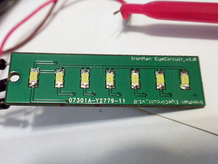
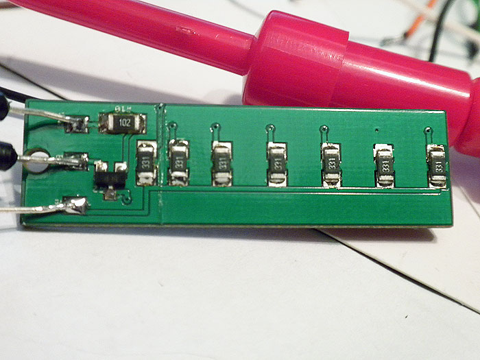
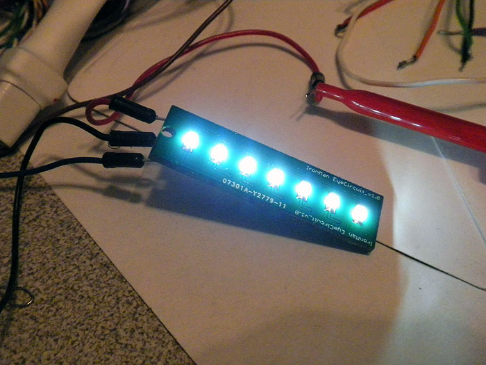
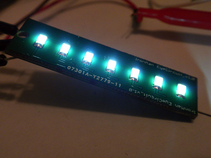
Electronics require to take your time understanding the basics. I had no idea how a transistor works a few month ago and now I've designed my board (50mm x 13mm)

Lots of info are in this thread. You can also find tutorials on youtube and on arduino forums.
You'll find help here but only if you come with precise questions and not "I want to do this and that, do it for me please, thanks, bye". (and I know, I asked many questions and pretty sure I'm a pain in the butt sometime ^^).
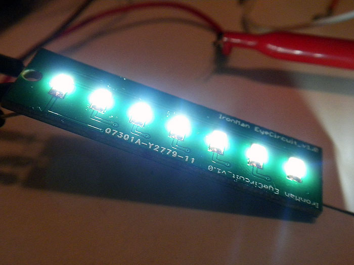
Electronics require to take your time understanding the basics. I had no idea how a transistor works a few month ago and now I've designed my board (50mm x 13mm)

") That's the way to learn (from the mistakes ^^).
That's the way to learn (from the mistakes ^^).