Iron man motorised faceplate electronics tutorial!!!

Hi all

I've been playing around a bit, and this is what I've added to the xl97's code;

Code:
// IronMan Helmet: eye blink sequence_v1.0
// created by: xl97

//import servo lib
#include <Servo.h>
//servo object names
Servo myservo; // create servo object to control a servo
//Servo myservo1;
const int buttonPin = 2; // the pin that the pushbutton is attached to
int buttonState = 0; // current state of the button
int lastButtonState = 0; // previous state of the button

// led control pins (need to be PWM enabled pins for fading)
const int leftEye =  6;  // the number of the left eye/pcb LEDs
const int rightEye =  3;  // the number of the right eye/pcb LEDs
const int readyLED =  4;  // the number of the Activate state LED
unsigned long fadeDelay = .5; //speed of the eye 'fade'
unsigned long callDelay = 700; //length to wait to start eye flicker after face plate comes down
unsigned long blinkSpeed = 100; //delay between init blink on/off
unsigned long currentPWM = 0;
boolean isOpen = true;
#define S_IDLE 1
#define S_ACTIVATE 12
#define S_LEDON 2
#define S_WAITON 3
#define S_LEDOFF 4
#define S_WAITOFF 5
#define S_INITON 6
#define S_INITWAIT 7
#define S_BLINKON 8
#define S_SERVOUP 9
#define S_SERVODOWN 10
#define S_SERVOWAIT 11
/*
This short program reads data from the  ADXL335 axis accelerometer
*/
const int groundpin = 18;             // analog input pin 4 -- ground
const int powerpin = 19;              // analog input pin 5 -- voltage
const int zpin = A3;                  // z-axis of the accelerometer
const int ypin = A2;                  // y-axis
const int xpin = A1;                  // x-axis
int tiltdown = 460;
int tiltup = 560;
const String XHEADER = "X: ";
const String YHEADER = "Y: ";
const String ZHEADER = "Z: ";
const String TAB = "\t";
long previousMillis = 0;              // will store last time the ACTIVATE state was triggered.
long interval = 5000;                 // the time spent in the active state waiting for tilt up before returning to idle.
long currentMillis = 0;               // will store the current time.
int faceUP = 0;                     // servo up position
int faceDOWN = 180;                     // servo down position
int servoDelay = 400;                 // delay required for servo to complete rotation before being disconnected.
//FSM init vars
static int state = S_IDLE; // initial state is 1, the "idle" state.
static unsigned long lastTime;  // To store the "current" time in for delays.

void setup() {
  // Set up serial port
  Serial.begin(9600);  
  //start it off
  //state = S_BLINKON; 
  Serial.print("INTIT STATE: ");
  Serial.println(state);
  myservo.attach(9); // attaches the servo on pin 9 to the servo object
  myservo.write(faceUP); // starts the servo in the Up position
  delay(servoDelay); // gives time for servo to complete rotation
  myservo.detach(); // detaches the servo to reduce jitter
  //myservo1.attach(10); // attaches the servo on pin 10 to the servo object
  pinMode(buttonPin, INPUT); // initialize the button pin as a input
  digitalWrite(buttonPin, HIGH); //use interal pull up resistors
  
  // initialize the serial communications:
  Serial.begin(9600);
  // Power and ground the necessary pins. Providing power to both
  // the analog and digital pins allow me to just use the breakout
  // board and not have to use the normal 5V and GND pins
  pinMode(groundpin, OUTPUT);
  pinMode(powerpin, OUTPUT);
  digitalWrite(groundpin, LOW);
  digitalWrite(powerpin, HIGH);
}
void loop() { 
  switch(state)
  {
  case S_IDLE:
    analogWrite(readyLED, 0);
    if (analogRead(xpin) < tiltdown) {
         previousMillis = millis();  // record the time the state changed
         Serial.print("WAITING FOR TILTUP");
         state = S_ACTIVATE;
    }
    else{
          Serial.print(XHEADER + analogRead(xpin) + " IDLE");
          Serial.println();
          delay(200);
    }
    break;
    
  case S_ACTIVATE:
    analogWrite(readyLED, 255);
    currentMillis = millis();  // determine the current time
    if (analogRead(xpin) > tiltup) {
       if(isOpen == true){
         Serial.print("CLOSING FACE PLATE: ");
         Serial.println(isOpen, DEC); 
         state = S_SERVODOWN;
       }
       else{
         Serial.print("OPENING FACE PLATE: ");
         Serial.println(isOpen, DEC); 
         //state = S_SERVOUP;
         state = S_LEDOFF;
       }
       isOpen = !isOpen;
    }
    else{
          if(currentMillis - previousMillis > interval) {
            Serial.print("Timed Out");
            state = S_IDLE;
          }
            Serial.print(XHEADER + analogRead(xpin) + " ACTIV");
            Serial.println();
            delay(200);
    }
    break;
  case S_BLINKON:
    Serial.println("init blink.........");   
    //do blink routine here
    //one blink
    analogWrite(leftEye, 155);
    analogWrite(rightEye, 155);
    delay(blinkSpeed);
    analogWrite(leftEye, 0);
    analogWrite(rightEye, 0);
    delay(10);
    //two blinks
    /*
    analogWrite(leftEye, 155);
     analogWrite(rightEye, 155);
     delay(blinkSpeed);
     analogWrite(leftEye, 0);
     analogWrite(rightEye, 0);
     delay(10);
     */
    state = S_LEDON;    
    break;
  case S_LEDON:
    Serial.println("increase........");    
    lastTime = millis();  // Remember the current time
    analogWrite(leftEye, currentPWM);
    analogWrite(rightEye, currentPWM);
    state = S_WAITON;  // Move to the next state
    break;
  case S_WAITON:
    // If one second has passed, then move on to the next state.
    if(millis() > (lastTime + fadeDelay)){
      if(currentPWM < 255){
        currentPWM += 5;
        state = S_LEDON;        
      }
      else{
        Serial.println("@ 255 done........");
        state = S_IDLE;
        //state = S_LEDOFF; //no auto turn off.. set to idle state
      }
    }
    break;
  case S_LEDOFF:
    Serial.println("........decrease");     
    lastTime = millis();  // Remember the current time
    analogWrite(leftEye, currentPWM);
    analogWrite(rightEye, currentPWM);
    state = S_WAITOFF;
    break;
  case S_WAITOFF:
    // If one second has passed, then move on to the next state.
    if(millis() > (lastTime + fadeDelay)){
      if(currentPWM > 0){  //change 0 to higher number to init face 'up' function sooner.
        currentPWM -= 5;
        state = S_LEDOFF;        
      }
      else{
        Serial.println("@ 0 done........");
        state = S_SERVOUP; //leds off..raise faceplate
      }
    }
    break; 
  case S_SERVOUP:
    Serial.println("servo up........."); 
    myservo.attach(9); // attaches the servo on pin 9 to the servo object
    myservo.write(faceUP);
    delay(servoDelay); // gives time for servo to complete rotation
    myservo.detach(); // detaches the servo to reduce jitter
    //myservo1.write(100);
    state = S_IDLE;    
    break;
  case S_SERVODOWN:
    lastTime = millis();  // Remember the current time
    Serial.println("servo down.........");   
    myservo.attach(9); // attaches the servo on pin 9 to the servo object
    myservo.write(faceDOWN);
    delay(servoDelay); // gives time for servo to complete rotation
    myservo.detach(); // detaches the servo to reduce jitter
    //myservo1.write(0);
    state = S_SERVOWAIT;    
    break;
  case S_SERVOWAIT:
    // If enough time has passed, call the eye flicker routine
    if(millis() > (lastTime + callDelay)){   
      Serial.println("start eye flicker routine");
      state = S_BLINKON;        
    }
    else{
      Serial.println("waiting........");
    }
    break;
  default:
    state = S_IDLE;
    break;
  } 
}

Here's where I got to with my previous version;

I used pretty much the same circuit he described in http://www.therpf.com/f78/iron-man-m...ml#post2936077 but as I'm using just one servo, I commented out all references to "myservo1" and both increased and reversed the values for "myservo".

As I didn't want my faceplate opening every time I looked up, I set the idle state to wait for me to look down first. This then triggers the activate state which waits for me to look up before either opening or closing the faceplate. It would be nice if this could time out so that I'd have to look down, then up within a few seconds to trigger the event, but I've not figured that bit out yet.

The amount I have to tilt my head can be adjusted with the "tilitdown" and "tiltup" values on lines 48 and 49.

I've now added the timer using millis (lines 55, 56, 57, 101, 130, 131 & 132). This only keeps the state as active for 5 seconds (line 56) before going back to idle.

I've also added an LED to pin 4, which lights up when the state is set to active - This will give me visual confirmation when wearing the helmet that it's ready to open (lines 20, 99 and 113).

Finally (for now), I detached the servo after each rotation (lines 60, 76, 77, 78, 209, 210, 211, 212, 220, 221, 222 & 223). I was getting a lot of jitter from the servo (apparently a common problem) which was not only causing an annoying noise, but was also causing the servo to heat up, and was also giving false readings to the accelerometer. Detaching the servo solved this. Once I have installed everything in the helmet, I will decide if I need to employ the xrobots servo braking system - https://www.youtube.com/watch?v=izr0zu-_Lyo

I'm happy for now - Though I'm sure someone smarter will offer a far better solution.
 
Last edited:
Hello

Was wondering if anyone could shed some light on my servo setup?

I've followed the instructions/guide at the start of this post but once the code is copied and pasted all that happens is my servos sit there jogging and the PC keeps making noises.

Is this a power issue?

Any help would be amazing.

P.S Go easy i'm new to all of this but love it just need some educated minds to guide ha ha

Most servo troubles fix themselves when you use external power(not USB).
 
Yup - use the same ground for the servos and Arduino, but give the servos 5-6v (4aa's are good). If you need braking, then have a look at the xrobots relay circuit, and/or use some small bungee cord.

Also, don't run a servo on pin 9. I'm not sure why, but it produces some weird results.
 
Also, don't run a servo on pin 9. I'm not sure why, but it produces some weird results.

There's nothing wrong in using the Pin 9 for servos on the Arduino, actually is better that you use the pins 9 and 10 for servos if you are running the servo library, due the fact that when this library is in use, the pin 9 and 10 loses the PWM function.

You were probably facing problems with loose connections or proper power delivery to the servos.

I happily stand corrected.
 
Here's a question maybe someone could help me out with... Is it possible to wire two separate buttons (or one pushbutton and one IR receiver) to perform the exact same task in the circuit? Basically I'm thinking I want to try an IR setup, but also want to have a regular push button wired somewhere in there as a backup, in case the IR has issues. I'd want the system to treat both inputs identically, as in I could press Button A OR Button B and the same code would be activated. How could this be wired so as not to clash with each other?
 
Here's a question maybe someone could help me out with... Is it possible to wire two separate buttons (or one pushbutton and one IR receiver) to perform the exact same task in the circuit? Basically I'm thinking I want to try an IR setup, but also want to have a regular push button wired somewhere in there as a backup, in case the IR has issues. I'd want the system to treat both inputs identically, as in I could press Button A OR Button B and the same code would be activated. How could this be wired so as not to clash with each other?

I assume that this is with an Arduino? If so, then your if statement could contain an "or";

http://forum.arduino.cc/index.php/topic,43582.0.html

That should allow you to use combinations of analogue of digital inputs to trigger an action.
 
Just wire the pushbutton and the RF to the same Digital I/O and it will work, make sure everything is well grounded and have fun!
 
I guess what I don't understand is this... I thought if a pushbutton was in one state no current goes through, and in the other state current will go through. But if I press button A once (stopping current) and then press button B... that button A will still be in the position preventing current from going through? Or vice versa...
 
I guess what I don't understand is this... I thought if a pushbutton was in one state no current goes through, and in the other state current will go through. But if I press button A once (stopping current) and then press button B... that button A will still be in the position preventing current from going through? Or vice versa...

You are thinking of wiring in series (one after the other like this --> + -------- in-A-out-------in-B-out-------- - )

The simplest way to do this is in parallel, like this:
in-A-out
|........|
in-B-out
| .......|
+.........-

***NOTE: I had to add the .... to put spaces between the "wires."

This way, for a normally open switch, if either switch is triggered, the circuit will close. The suggestion above about wiring both switches to the same I/O pin is the same thing as wiring in parallel.

The suggestion about handling it in software would work as well, but I guess I've always figured if I can do it in hardware and save the software resources for something else, that's the way I go.

I hope my little diagrams make sense....
 
All good advice, as it seems to be working (although I haven't tried it on the full circuit yet, just on simple LEDs).

So my next dilemma/idea... for my repulsors I want to have 3 modes: Off, Always On, and On when triggered by a tilt switch. This way I could leave them on for certain photo poses, but also have an 'action' trigger mode as well. I figure this is something like a fan with three settings: High, Low, and Off. So if the switch is on one setting, the power goes right to the light and it stays on (I've done this). In the other setting, there would be a tilt switch in the middle triggering the light (I've got this to work as well). And the third setting would just be off, so I could move my hands around freely without wasting battery.

I found this:
416aEuQEo8L._SY300_.jpg
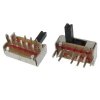
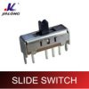
8 Pin ON/ON/ON 3 Position 2P3T Mini Horizontal Slide Switch and I think it's what I need, but I'm not 100%.

Also I have no idea how to actually wire this thing up. Note: the idea is to use this without an Arduino or anything like that.

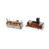
I also see there are 1P3T (or SPTT) switches as well, with only 4 pins. Would that do the job instead?
31tZanQR8yL._SY300_.jpg

Has anyone worked with 2P3T or 1P3T switches? Would they do what I'm looking for, and how?
 

Attachments

  • _font_b_1p3t_b_font_mini.jpg_140x140.jpg
    _font_b_1p3t_b_font_mini.jpg_140x140.jpg
    7.5 KB · Views: 807
Can someone help me with my set up? I set it up exactly how instructed in the first post and it doesnt work. The LED works but the servos dont. They just make this high pitched noise. Whats wrong with mine?1410415469204.1.jpg
 
who can help out I have a older sketch that gets an error on upload:

Wtv020sd16p' does not name a type

highlights this> Wtv020sd16p wtv020sd16p(resetPin,clockPin,dataPin,busyPin);

any suggestions ???
 
If this helps you think a older version would up load it??

/*
Example: Control a WTV020-SD-16P module to play voices from an Arduino board.
Created by Diego J. Arevalo, August 6th, 2012.
Released into the public domain.
*/

#include <Wtv020sd16p.h>

int resetPin = 2; // The pin number of the reset pin.
int clockPin = 3; // The pin number of the clock pin.
int dataPin = 4; // The pin number of the data pin.
int busyPin = 5; // The pin number of the busy pin.

/*
Create an instance of the Wtv020sd16p class.
1st parameter: Reset pin number.
2nd parameter: Clock pin number.
3rd parameter: Data pin number.
4th parameter: Busy pin number.
*/
Wtv020sd16p wtv020sd16p(resetPin,clockPin,dataPin,busyPin);

void setup() {
//Initializes the module.
wtv020sd16p.reset();
}

void loop() {
//Plays synchronously an audio file. Busy pin is used for this method.
wtv020sd16p.playVoice(0);
//Plays asynchronously an audio file.
wtv020sd16p.asyncPlayVoice(1);
//Plays audio file number 1 during 2 seconds.
delay(5000);
//Pauses audio file number 1 during 2 seconds.
wtv020sd16p.pauseVoice();
delay(5000);
//Resumes audio file number 1 during 2 seconds.
wtv020sd16p.pauseVoice();
delay(5000);
//Stops current audio file playing.
wtv020sd16p.stopVoice();
//Plays synchronously an audio file. Busy pin is used for this method.
wtv020sd16p.asyncPlayVoice(2);
delay(2000);
//Mutes audio file number 2 during 2 seconds.
wtv020sd16p.mute();
delay(2000);
//Unmutes audio file number 2 during 2 seconds.
wtv020sd16p.unmute();
delay(2000);
//Stops current audio file playing.
wtv020sd16p.stopVoice();
}
 
I cant tell for sure.. but it looks as if you are trying to power the servos from the Arduino itself..

try powering from an external source.. and connecting all grounds together.

All good advice, as it seems to be working (although I haven't tried it on the full circuit yet, just on simple LEDs).

So my next dilemma/idea... for my repulsors I want to have 3 modes: Off, Always On, and On when triggered by a tilt switch. This way I could leave them on for certain photo poses, but also have an 'action' trigger mode as well. I figure this is something like a fan with three settings: High, Low, and Off. So if the switch is on one setting, the power goes right to the light and it stays on (I've done this). In the other setting, there would be a tilt switch in the middle triggering the light (I've got this to work as well). And the third setting would just be off, so I could move my hands around freely without wasting battery.

I found this:
View attachment 364751
8 Pin ON/ON/ON 3 Position 2P3T Mini Horizontal Slide Switch and I think it's what I need, but I'm not 100%.

Also I have no idea how to actually wire this thing up. Note: the idea is to use this without an Arduino or anything like that.

I also see there are 1P3T (or SPTT) switches as well, with only 4 pins. Would that do the job instead?
View attachment 364778

Has anyone worked with 2P3T or 1P3T switches? Would they do what I'm looking for, and how?
 
Back
Top