You are using an out of date browser. It may not display this or other websites correctly.
You should upgrade or use an alternative browser.
You should upgrade or use an alternative browser.
Iron man motorised faceplate electronics tutorial!!!
- Thread starter 7sinzz
- Start date

xl97
Master Member
what is the second pcb for? an A-I-O board of some kind?
What are the leds on there for? (the eyes?) on-board?
maybe think of a modular approach? (transistors, resistors, pcb's for just the eyes that connect to the main/brain)
a board for the servos to connect to? (vregulator, connections)
links to diagrams:
http://www.therpf.com/showthread.php?t=170853&page=49&p=3041287&viewfull=1#post3041287
eye pcb:
http://www.therpf.com/showthread.php?t=170853&page=49&p=3040927&viewfull=1#post3040927
video: (of it all in-action, minus helmet)
https://www.youtube.com/watch?v=cTXt8l2XH-Q
stang67
Active Member
I am still new at this. I believe I 'm now caught up to page 41 of this Thread.
Not sure what you mean by the second board. One is the arduino mini pro the other is the voltage regulator, resistors and transistors for me to hook everything up to. I couldn't think of another way to do it. My approach,I thought was similar to what your referring to.
Not knowing any better my thought was the leds are simply a place holder for the wires to hook to. No leds will be on this board, just the wire connection leading to the led Eyes. Not real sure what I was thinking giving myself a total of six areas to connect leds Really not necessary. At least this way it can be regulated on the board.
So I was hoping to put permanent leads on the board with connectors to attach to the servo's and eyes.
Did I make this more complicated that it is?
Those Eyes you made are awesome BTW! I'm not ready for SMD but I will get there.
xl97
Master Member
I'm not saying anything you are doing is wrong.. (its your project).. I was just trying to understand what you had posted.
Having ht eleds and transistors..etc.. and servo hook-ups..etc..etc all on one board was a bit mis-leading when your just looking at the pics.
I had no clue how you were going to get them to fit in the eye sockets..etc.
IMHO.. all eye stuff should be on 1 board.. (in case of failure.. easy to replace)....
Ad for the eyes PCB's I made.. you can do the same.. but with through hole components..")
then all you needs is the wires from eye pcb to arduino.. (no middle man) since the leds will still have to me mounted to 'something'.. (why not its own pcb with all needed components on it?)
In the end if it works for you! great!. Thats what this is all about. Having fun learning and working toward a goal!
As far as SMD stuff.. it only seems scary! (at first).. lol..
but with a small investment, you can be baking your own SMB pcb's in no time.
I invested in vinyl cutter (not only for stickers and stuff.. but also so I can cut solder masks/stencils to lay over my pcb's smear some solder paste over it.. remove stencil..
place my smd components on the board.. and throw it in my $17 toaster oven from wal-mart! bake for 3-5 minute.s. until I see solder start to re-flow.. and bang! all done!
Add wires and fire it up!
not sure if you have gotten past page 41 yet.. but I think some diagrams are posted after that?
Anyways.. good luck! I'm sure things will turn out great!
Having ht eleds and transistors..etc.. and servo hook-ups..etc..etc all on one board was a bit mis-leading when your just looking at the pics.
I had no clue how you were going to get them to fit in the eye sockets..etc.
IMHO.. all eye stuff should be on 1 board.. (in case of failure.. easy to replace)....
Ad for the eyes PCB's I made.. you can do the same.. but with through hole components..
then all you needs is the wires from eye pcb to arduino.. (no middle man) since the leds will still have to me mounted to 'something'.. (why not its own pcb with all needed components on it?)
In the end if it works for you! great!. Thats what this is all about. Having fun learning and working toward a goal!
As far as SMD stuff.. it only seems scary! (at first).. lol..
but with a small investment, you can be baking your own SMB pcb's in no time.
I invested in vinyl cutter (not only for stickers and stuff.. but also so I can cut solder masks/stencils to lay over my pcb's smear some solder paste over it.. remove stencil..
place my smd components on the board.. and throw it in my $17 toaster oven from wal-mart! bake for 3-5 minute.s. until I see solder start to re-flow.. and bang! all done!
Add wires and fire it up!
not sure if you have gotten past page 41 yet.. but I think some diagrams are posted after that?
Anyways.. good luck! I'm sure things will turn out great!
stang67
Active Member
I took your response as constructive criticism! Which is what I wanted from my post. I thank you for that. It made me take a look at it again and what was confusing. I have redesigned the board as a Shield. I had no idea that's why the second board was there. I just thought it was there for reference. Now that I have it as a shield it much cleaner to attach to the arduino but a bit larger.
I'm with you on the eye PCB Iv'e been looking at what you made and would like to do something similar. I'm not afraid of SMD's , there is still much for me to learn, one major thing is the Eagle software , not as user friendly as Fritzing.
I'm interested in the vinyl cutter and how you use that with the boards. I have a Cameo sihouette., which I believe is able to cut vinyl. I'll look up how to do that. Maybe you have a link to a tutorial.
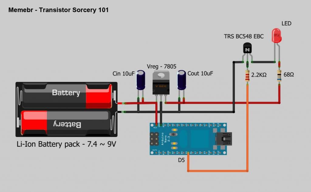
Worked on this tonight. Hopefully I did it right. and If I did I hope I can make it.
I would use 2 capacitors on the 7805 regulator for a smooth output. (it is not present on my V1, but works like a charm if added)
mounted as shown on this pic
Also, the army is killing me, a lot of work and almost no free time.
Last edited:
stang67
Active Member
Thanks Memebr! I revised my board this weekend to include the capacitors. Still got work to do on it. I went and made the board I posted prior to seeing that caps are recommended. I stared to make the circuit as I was catching up on the thread. I felt I learned better. I am using a variant of the Vreg-7805 as you show and on the spec sheet from the one I purchased it recommends a .33uf and a .1uf I believe. I'm sure there are many different requirements from different manufacturers. I think you may have shown those values on one of your earlier posts.
I am trying to learn The eagle program , I really want to learn how to do the SMD board for the eyes. I think i'm going to leave the transistors on the main board though, mainly because there are so many different models and I have no clue yet on how to pick the correct one. So The main board will most like stay as a through hole.
I am trying to learn The eagle program , I really want to learn how to do the SMD board for the eyes. I think i'm going to leave the transistors on the main board though, mainly because there are so many different models and I have no clue yet on how to pick the correct one. So The main board will most like stay as a through hole.
I am using a variant of the Vreg-7805 as you show and on the spec sheet from the one I purchased it recommends a .33uf and a .1uf I believe. I'm sure there are many different requirements from different manufacturers.
use 2 10uf @ 35V caps, this way when you add load, things are not going to be messy. At my tests the 1uF and .33uF caps were not enough when variable load (servos) was applied.
Also, most of the 78XX series are the same thing, no matter who manufactures them. About the transistors use the same ones i used, they are fairly common and easy to find on the market, if you are using 2 like i used on the V1 circuit you can use any NPN with 200mA. the BC548 is one of those you can use (it will hold 8 or 9 leds @ 20mA)
crimsondante
New Member
I am completely lost on this i followed the instructions on page 1 and nothing happens, Can some one have a look at what i am doing wrong ?
stang67
Active Member
Post a picture of your set up. Do it straight down on it That's the only way anyone can can check your work.I am completely lost on this i followed the instructions on page 1 and nothing happens, Can some one have a look at what i am doing wrong ?
Some advice would be to double check all of your wiring to be sure it is correct. The instructions are pretty straight forward. be sure to read this thread.
crimsondante
New Member
Post a picture of your set up. Do it straight down on it That's the only way anyone can can check your work.
Some advice would be to double check all of your wiring to be sure it is correct. The instructions are pretty straight forward. be sure to read this thread.
Ok thanks i re followed the instructions and still nothing
then i decided to look at the programming of the Ad uno, it was selected to the wrong com port
so now it all works
but the servo just hisses ? like its under strain ?
Last edited:
stang67
Active Member
Ok . So nothing was uploaded to the Arduino when you first tried.?Ok thanks i re followed the instructions and still nothing
then i decided to look at the programming of the Ad uno, it was selected to the wrong com port
so now it all works
but the servo just hisses ? like its under strain ?
Read more of this thread. There were some people here that had the same issue. Could be the range of the servo's . They don't truly turn 180. I had to set mine to 15 and 150 to stop the buzzing. yours may be different values. You'll need to play around to see what works.
Dread Lensman
New Member
This is the servo lock using a relay that xrobots used in his video: https://www.youtube.com/watch?v=izr0zu-_Lyo

I'm just not sure how to edit the code to utilize it. Any help would be appreciated, thanks.
I'm just not sure how to edit the code to utilize it. Any help would be appreciated, thanks.
xl97
Master Member
I took your response as constructive criticism! Which is what I wanted from my post. I thank you for that. It made me take a look at it again and what was confusing. I have redesigned the board as a Shield. I had no idea that's why the second board was there. I just thought it was there for reference. Now that I have it as a shield it much cleaner to attach to the arduino but a bit larger.
I'm with you on the eye PCB Iv'e been looking at what you made and would like to do something similar. I'm not afraid of SMD's , there is still much for me to learn, one major thing is the Eagle software , not as user friendly as Fritzing.
I'm interested in the vinyl cutter and how you use that with the boards. I have a Cameo sihouette., which I believe is able to cut vinyl. I'll look up how to do that. Maybe you have a link to a tutorial.
Hey stang-
I too have the Silhoutte Cameo vinyl cutter... and that sis what I use to make my SMD solder paste stencils.
All the tuts on using the stock software to convert a .dxf/.dwg (whatever) file just dont turn out that great for me.
Go to Dangerous Prototypes forum/blog and search for topic of making solder past stencils..etc
and you will be given the bible! lol
It does have some files/apps you need to install.. and the work-flow/tool-chain takes 3-5 times to get used to.. but it makes great stencils..
I havent paid for one since I got my Cameo! (and they go for $20-$35 a pop!)
As far as Eagle.. it is a bit akward.. but stick with it.. and you'll have no problems.. it has HUGE community support, tutorials, files.. add-ons..etc so "I" prefer it.
That being said.. it is also a bit backwards then our normal working lives..
normally (liek in WORD for example).. you highlight your selcetion... then click on a button to add that effect/style to the selected object.
Eagle works the other way... you click on the TOOL you want first.. then select the object you want ti applied too.
ALso.. it was DESIGNED to be used with a 3 button mouse.. so much about and left, middle, right click on objects/stage..etc to get familiar with the options you get there.
(I think clicking the middle/mouse wheel lets you drag the stage around..)
There are literally lists of tips and tricks for eagle though.. when you get some downtime, google it.
xl97
Master Member
crimsondante-
Are your GND's connected?
Are the servo's under load? (lifting anything)
Have you tried the basic servo tutorials on the 'net, to ensure things worked properly before starting this circuit/project?
How are you powering the servo? (not from the Arduino I hope.. it will burn out@!)
Are your GND's connected?
Are the servo's under load? (lifting anything)
Have you tried the basic servo tutorials on the 'net, to ensure things worked properly before starting this circuit/project?
How are you powering the servo? (not from the Arduino I hope.. it will burn out@!)
Last edited by a moderator:
stang67
Active Member
Hey stang-
I too have the Silhoutte Cameo vinyl cutter... and that sis what I use to make my SMD solder paste stencils.
All the tuts on using the stock software to convert a .dxf/.dwg (whatever) file just dont turn out that great for me.
Go to Dangerous Prototypes forum/blog and search for topic of making solder past stencils..etc
and you will be given the bible! lol
It does have some files/apps you need to install.. and the work-flow/tool-chain takes 3-5 times to get used to.. but it makes great stencils..
I havent paid for one since I got my Cameo! (and they go for $20-$35 a pop!)
As far as Eagle.. it is a bit akward.. but stick with it.. and you'll have no problems.. it has HUGE community support, tutorials, files.. add-ons..etc so "I" prefer it.
That being said.. it is also a bit backwards then our normal working lives..
normally (liek in WORD for example).. you highlight your selcetion... then click on a button to add that effect/style to the selected object.
Eagle works the other way... you click on the TOOL you want first.. then select the object you want ti applied too.
ALso.. it was DESIGNED to be used with a 3 button mouse.. so much about and left, middle, right click on objects/stage..etc to get familiar with the options you get there.
(I think clicking the middle/mouse wheel lets you drag the stage around..)
There are literally lists of tips and tricks for eagle though.. when you get some downtime, google it.
Thanks xl97 Took a look at that site .. Thank you! Watched a few tutorials on Eagle too on You Tube. Gonna take me some time but I'll get "OK" at it soon enough. Just need time to play with it more. As you said its really not that hard just backward.
Been trying to make the board I designed in Fritzing But having trouble using the "Toner Transfer method" on magazine paper. Found out my Iron gets super hot on high and was turning the toner into liquid, Making it bleed all aver the board. I finally got the temp right just need to get the right amount of pressure applied for the right amount of time. Hopefully I'll get a usable transfer this week so I can test out the board. Then I may send out for them to be made.(Where do you get yours made?) I have to make a total of 5. One for me and a friend and the other 3 for my kids.
xl97
Master Member
For home brew PCB etching..
I use glossy printer paper.. using a LASER printer (that is important....not a ink/bubble jet printer)
and then iron it to my copper clad board...
then soak/etch..
lastly.. populate/test board.
for PCB fabrication... it depends.
Do I need it quick? Am I on a budget?
Do I need the best quality available for DIY/hobby use?
I have used several PCB fab houses..
iTeadStudio/iMall - used
Seeed - used
OSHPark
Elecrow - used
Sitopway
iteadStudio -
(currently merged into iMall)
http://imall.iteadstudio.com/open-pcb/pcb-prototyping.html
*(I have used these guy..love them,..but I only get really small boards usually)
SeeedStudio -
(very similar to iTeadStudio)
http://www.seeedstudio.com/depot/fusion-pcb-service-p-835.html
Sitopway (Technology Limited) -
(new, but has bigger pcb size for their smallest package/cost compared to the two above)
http://www.sitopway.com/en/index.php
I believe all are located in China somewhere.. (and may even used the same fabrication service?)
They all offer their own perks (pros/cons)..
some have more size available.
some have a bit better pricing
some offer free colored pcb's...etc
in the end they are mostly the same.. decent/good quality. I havent had any problems with any of the boards I have gotten made. Shipping time sucks...lol.
OSHPark is in the US.. more money.. but are known (and I have seen some first hand) for great quality (and their purple/gold color/branding)
Some place charge you buy the inch.. while most of the Chinese places charge by over-all size. and you get about 10 pcbs for about $10-15 USD for small boards.. which is great for small prototyping runs..
Last edited by a moderator:
stang67
Active Member
Wow some good sites there. Thank you very much!
I tried the photo paper. Got it to transfer great but ended up damaging the toner way too bad after soaking and scraping.
Finally got a good Usable transfer last night using magazine paper in my laser printer.

Got it etched and drilled. Can't wait to get time to test it!
Thinking of investing in the PCB "Fab in a Box" KIt and getting the lamination machine they recommend. Seams like a good process and many have had good success with it. also looked at the MG Chemicals Photo fabrication kit. It is a toss up for me as to which way I will go. One of the kits or sending out for fab. Having it NOW might win.
I tried the photo paper. Got it to transfer great but ended up damaging the toner way too bad after soaking and scraping.
Finally got a good Usable transfer last night using magazine paper in my laser printer.
Got it etched and drilled. Can't wait to get time to test it!
Thinking of investing in the PCB "Fab in a Box" KIt and getting the lamination machine they recommend. Seams like a good process and many have had good success with it. also looked at the MG Chemicals Photo fabrication kit. It is a toss up for me as to which way I will go. One of the kits or sending out for fab. Having it NOW might win.
Dread Lensman
New Member
I added relays to xl97's eyeblink code, attaching them to pins 7 and 8, and writing them high and low. The code compiles, but I haven't built the circuit yet. Any pointers with the code would be greatly appreciated.
// IronMan Helmet: eye blink sequence_v1.0
// created by:
// Movie Props, Costumes and Scale Models | the RPF thread:
// http://www.therpf.com/f24/iron-man-m...ml#post2647126
//import servo lib
#include <Servo.h>
//servo object names
Servo myservo; // create servo object to control a servo
Servo myservo1;
const int buttonPin = 2; // the pin that the pushbutton is attached to
int buttonState = 0; // current state of the button
int lastButtonState = 0; // previous state of the button
int pos = 0; // variable to store the servo positions
int pos1 = 180;
// led control pins (need to be PWM enabled pins for fading)
const int leftEye = 6; // the number of the left eye/pcb LEDs
const int rightEye = 3; // the number of the right eye/pcb LEDs
// relay control pins
int myservoLock = 7;
int myservo1Lock = 8;
unsigned long delaytime = 1;
unsigned long blinkspeed = 100;
unsigned long currentPWM = 0;
boolean isOpen = true;
#define S_IDLE 1
#define S_LEDON 2
#define S_WAITON 3
#define S_LEDOFF 4
#define S_WAITOFF 5
#define S_INITON 6
#define S_INITWAIT 7
#define S_BLINKON 8
#define S_SERVOUP 9
#define S_SERVODOWN 0
//FSM init vars
static int state = S_IDLE; // initial state is 1, the "idle" state.
static unsigned long lastTime; // To store the "current" time in for delays.
void setup() {
// Set up serial port
Serial.begin(9600);
//start it off
//state = S_BLINKON;
Serial.print("INTIT STATE: ");
Serial.println(state);
myservo.attach(9); // attaches the servo on pin 9 to the servo object
myservo1.attach(10); // attaches the servo on pin 10 to the servo object
pinMode(buttonPin, INPUT); // initialize the button pin as a input
digitalWrite(buttonPin, HIGH); //use interal pull up resistors
pinMode(myservoLock, OUTPUT); // Set up relays as outputs
pinMode(myservo1Lock, OUTPUT);
}
void loop() {
switch (state)
{
case S_IDLE:
// We don't need to do anything here, waiting for a forced state change...like button press.
//check mian button state
buttonState = digitalRead(buttonPin);
// compare buttonState to previous state
if (buttonState != lastButtonState) {
//if button pressed/down
if (buttonState == LOW) {
//ie: pressed
if (isOpen == true) {
Serial.print("CLOSING FACE PLATE: ");
Serial.println(isOpen, DEC);
state = S_SERVODOWN;
}
else {
Serial.print("OPENING FACE PLATE: ");
Serial.println(isOpen, DEC);
//state = S_SERVOUP;
state = S_LEDOFF;
}
isOpen = !isOpen;
}
else {
//went from ON/HIGH to LOW/OFF..ie: released
//Serial.print("RELEASE: ");
//Serial.println(isOpen, DEC);
}
}
// save the current state for next loop
lastButtonState = buttonState;
break;
case S_BLINKON:
Serial.println("init blink.........");
//do blink routine here
analogWrite(leftEye, 155);
analogWrite(rightEye, 155);
delay(blinkspeed);
analogWrite(leftEye, 0);
analogWrite(rightEye, 0);
delay(10);
/*
analogWrite(leftEye, 155);
analogWrite(rightEye, 155);
delay(blinkspeed);
analogWrite(leftEye, 0);
analogWrite(rightEye, 0);
delay(10);
*/
currentPWM = 0;
state = S_LEDON;
break;
case S_LEDON:
Serial.println("increase........");
lastTime = millis(); // Remember the current time
analogWrite(leftEye, currentPWM);
analogWrite(rightEye, currentPWM);
state = S_WAITON; // Move to the next state
break;
case S_WAITON:
// If one second has passed, then move on to the next state.
if (millis() > lastTime + delaytime)
{
if (currentPWM < 255) {
currentPWM += 5;
state = S_LEDON;
}
else {
Serial.println("@ 255 done........");
state = S_IDLE;
//state = S_LEDOFF; //no auto turn off.. set to idle state
}
}
break;
case S_LEDOFF:
Serial.println("........decrease");
lastTime = millis(); // Remember the current time
analogWrite(leftEye, currentPWM);
analogWrite(rightEye, currentPWM);
state = S_WAITOFF;
break;
case S_WAITOFF:
// If one second has passed, then move on to the next state.
if (millis() > lastTime + delaytime)
{
if (currentPWM > 0) {
currentPWM -= 5;
state = S_LEDOFF;
}
else {
Serial.println("@ 0 done........");
state = S_SERVOUP; //leds off..raise faceplate
}
}
break;
case S_SERVOUP:
digitalWrite(myservoLock, HIGH); // Close relays, deactivate the lock
digitalWrite(myservo1Lock, HIGH);
myservo.write(100);
myservo1.write(100);
digitalWrite(myservoLock, LOW); // Open relays, activate lock
digitalWrite(myservoLock, LOW);
//delay(20); //wait to trigger the led flicker.. will remove delay() use in next revision
state = S_IDLE;
Serial.println("servo up.........");
break;
case S_SERVODOWN:
digitalWrite(myservoLock, HIGH); // Close relays, deactivate the lock
digitalWrite(myservo1Lock, HIGH);
myservo.write(0);
myservo1.write(0);
delay(20); //wait to trigger the led flicker.. will remove delay() use in next revision
state = S_BLINKON;
digitalWrite(myservoLock, LOW); // Open relays, activate lock
digitalWrite(myservoLock, LOW);
Serial.println("servo down.........");
break;
default:
state = S_IDLE;
break;
}
}
Similar threads
- Replies
- 1
- Views
- 337
- Replies
- 1
- Views
- 511
- Replies
- 2
- Views
- 613