It sort of does - I have a very vague hunch...
There's a simple possibility:
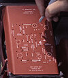
these two dots on each side may just be screws,
View attachment 1382669
View attachment 1382670and these two aluminium strips, along each side of the bottom, are for those screws to tap into,
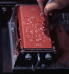
and there could just be tapped holes here:
View attachment 1382671
Which would make life easy and I'd certainly start with that (because those two strips are easy to just unscrew and replace when a better idea presents itself).
But there
does seem to be something else there, which reminds me of spring-steel clips I've seen when trawling through aviation engineering stuff - sheet-metal fixings, captive-nut type things.. But I don't see the need when there are two nice big chunks of aluminium to screw into directly.
Maybe as you say these are just springy clips for the top to snap over, though the folded sheet-metal top will already be naturally very springy and so need some more secure fixing..
Looking forward to seeing you guys work it out when you build it!
It's the best we got, though. The typeface at the bottom definitely looks like Futura Bold, like other sets and props in the film.