Daft Punk Thomas Bangalter helmet build - FINAL p.20!

Re: Daft Punk Thomas Bangalter helmet build

D-D-D-Double-post!

Sorry for the self bump, but got some progress to show.

A while back I posted a mockup rig for the LED subvisor:

5537541714_4b2d343605_b.jpg


I went back and forth on the dimensions for a while, trying to figure out the best spacing between the LEDs and the visor, and also between the LEDs themselves. Even small changes will result in a pretty drastic overall shift in the layout of the grid, so this is a project I've been subconsciously putting off for a little while... Finally took the plunge last night.

I settled on a sheet of .063" Aluminum sheet for the upper and lower frames, to be held in place with thick-walled aluminum tube stock, threaded for countersunk screws. This is one of those times I really with I had access to a laser cutter.

Top plate:

5737039026_f1bece7651_b.jpg


Bottom plate:

5737039096_26e7db58c3_b.jpg


After a LOT of time on my scrollsaw & drill press, I had these. The multiple-circle areas in the middle is where I'll be mounting ventilation fans, situated directly above the "nose vents" on the underside of the visor.

5737039188_0b15a74cb9_b.jpg


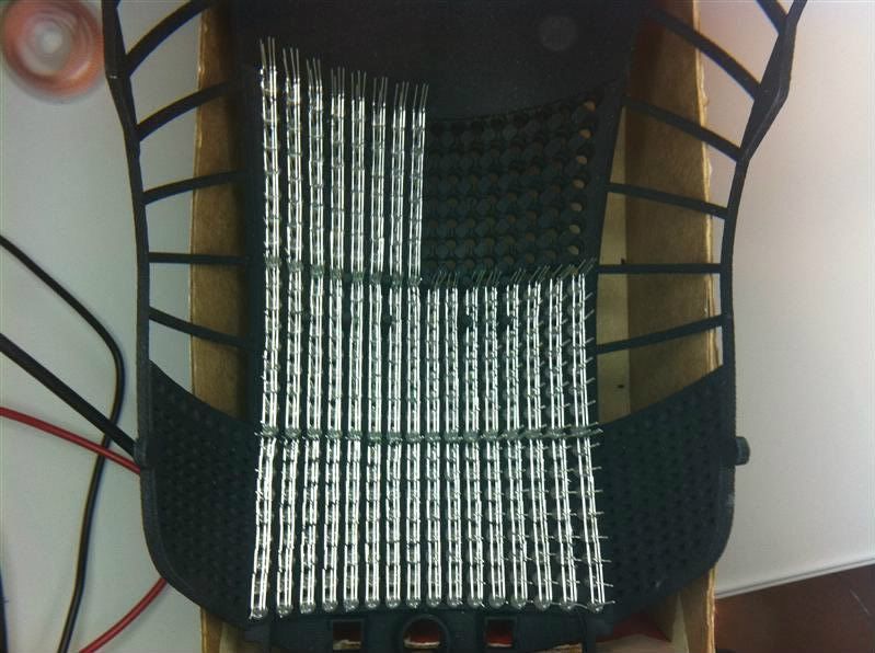
The result at the end of the evening:

5736487599_16d8499e60_b.jpg


I still need to countersink a few of the holes slightly deeper, and a few of the rods need to be tapped further to allow the screws to sit fully flush. There's a bunch more holes that need to be drilled and cut (for wire routing, mounting, and to hold the PET subvisor in place) but this is the basic jist of things. Really happy with how its looking so far, can't wait to get some circuitry on it!

5737039254_16672df150_b.jpg
 
Re: Daft Punk Thomas Bangalter helmet build

I said it on Flickr and I'll say it here, the the way you are doing the fans is pretty ingenious.

I have no real proof to base this off of, but I doubt the real helmet had fans in it like this. So between the wireless iPhone app, and these fans, your helmet is truly going to be better than the real thing!
 
Re: Daft Punk Thomas Bangalter helmet build

^I agree with Raybans, this is an serious upgrade over the original.
 
Re: Daft Punk Thomas Bangalter helmet build

Its possible, I might give that a shot but the fisheyes honestly aren't all that bad to deal with. When you mold yours (and, also, if you're using pre-made registration keys like I did) make sure that they're stuck on with a lot of thickened silicone so the likelihood of getting trapped air is minimized.


Ah sorry, i thought you had meant that there was air getting stuck between the silicone registration keys and the master female keys if you know what i mean.. but its air stuck between the molded egg yolk shaped keys and the actual silicone mold itself?

Good to see some more progress.. been waiting on this for a while ;) its looking good

like you say, a laser cutter would be useful. I have plans to laser cut these parts from acrylic... :) Not boasting or anything :p

Mike
 
Re: Daft Punk Thomas Bangalter helmet build

like you say, a laser cutter would be useful. I have plans to laser cut these parts from acrylic... :) Not boasting or anything :p

Not all of us can be so lucky, I guess. The build process right now, at least for this component, is a sort of "working prototype." I didn't know exactly what I was going to do or how certain components would fit before I started building it. I couldn't really have files sent out to be laser-cut, as the patterns still aren't done yet.

Once these parts are finished I may scan them in and make vector templates for if I ever decide to repeat the project or if someone else wants to use them.

For now though, I think my scroll saw works just fine.

Perfect example: Initially, I had intended to cut the subvisor from PET sheet, then bend tabs on the PET to overlap the aluminum frame and be screwed into place. While trimming the sections, it occurred to me that I could make slots in the visor frame to hold everything in place instead - just friction fit, no screws or glue to mess up the clarity of the subvisor.

Pictures will make more sense:

5738488521_2e9c4d1923_b.jpg

5738488425_697a2377a8_b.jpg


You can see the series of slots along the front edge of the frames. The subvisor itself has a sort of toothed edge that slots into these. This holds it rigidly in place, while also bending it to shape. The mockup here is styrene, just a proof of theory with cheap stuff before I start cutting out the PET. I'm really happy with the result.

Here's a shot of it in my test helmet, to give you an idea of placement. Still need to work on mounting points.

5739041850_0bc0b8dea7_b.jpg


More to come after this weekend
 
Re: Daft Punk Thomas Bangalter helmet build

Wow, those are exeptional ideas , awesome job Harrison !
(Please check your PMs !)
 
Re: Daft Punk Thomas Bangalter helmet build

Not sure if you've seen this yet, but I am pretty sure this is one of your helmets

tumblr_lliq64kJtV1qzpksgo1_1280.jpg


Looks mighty good chromed up! All I know about the picture is it was taken at Anime Central.

Edit:

Found another one of the same pair.

tumblr_llj1klesAL1qcmjxf


Looks like one of your Guy-Man's, too. Funny how setting the visor from the inside can change the look so much.
 
Last edited:
Re: Daft Punk Thomas Bangalter helmet build

Oh, nice. I want to know where those guys got their jackets, looks like a great close enough.
 
Re: Daft Punk Thomas Bangalter helmet build

Not sure if you've seen this yet, but I am pretty sure this is one of your helmets

Looks like one of your Guy-Man's, too. Funny how setting the visor from the inside can change the look so much.

Interesting. Definitely one of my Thomas buckets. If the Guy is mine, the chin has been remade pretty extensively. I don't think it is, but its tricky to know for sure.

Thomas does look good with a coat of paint, thats for sure. Nice to see one thats been finished!
 
Re: Daft Punk Thomas Bangalter helmet build

Everything is looking GREAT Harrison!

That visor setup is pretty smexy. Just out of curiosity, what reasons did you have for using metal for the visor bracket? Vs, say... basswood.
 
Re: Daft Punk Thomas Bangalter helmet build

Everything is looking GREAT Harrison!

That visor setup is pretty smexy. Just out of curiosity, what reasons did you have for using metal for the visor bracket? Vs, say... basswood.

Countersinking and hole tapping! Also, there's humidity to be considered. I could go with a denser plastic like acrylic or nylon, but aluminum was easy to get a hold of and easy to work with as well.

So, more to file under the "Gee, wouldn't having a laser cutter be nice?" category. The subvisor PET panel:

Started out by spray mounting the template to the protective film on one side of the PET. I am eternally thankful for the laser guides on my drill press.

5751200531_88abcc03f5_b.jpg


About an hour or so later, I had this:

5751744522_e40416cff9_b.jpg


And then the whole piece was trimmed to shape on the scrollsaw

5751744580_9bf85ae566_b.jpg


Here's the piece mounted in the visor plates for a test-fit. There's still one side of the protective film on there, to protect it during handling. I'll remove this when I'm ready to solder the LEDs. I'll also be shaving down the mounting tabs at that time as well.

5751200847_100ef83ec9_b.jpg


To make mounting the boards easier, I drilled and tapped holes in the upper visor section for the MAX72XX chip boards.

5751744626_e6ec0b8dba_b.jpg


Then... I decided to polish the mounting plates. Superfluous? Probably. Cool looking? Yes.

5751200809_63a7c99047_b.jpg


And a few mockups with some of the components laid into place. I've got a LOT of soldering coming up in my future!

5751744914_236f5b2510_b.jpg

5751745024_8be00aea71_b.jpg
 
Re: Daft Punk Thomas Bangalter helmet build

Welcome to my nightmare mate :unsure

IMG_0548.jpg


Closeup

That's five 8x8 matrices done. I've actually done another 2 rows just a few minutes ago. Actually, they're not 'done,' just the RGB columns. I've still got the common anode rows and the jumpers left to do, according to my math. So right now I've done 294/1104 solder joints. Only 73.4% left to go :rolleyes

FYI: forgive the fish-eye in the picture, I was using my fluorescent magnifier as a macro lens.

EDIT:
Volpin, be woefully careful about attaching circuit board to a conductive fame, i.e. the aluminum subframe. Can't tell you how much MBS (magic blue smoke) has been released by myself alone being naff and forgetting standoffs.
 
Last edited:
Re: Daft Punk Thomas Bangalter helmet build

Volpin, be woefully careful about attaching circuit board to a conductive fame, i.e. the aluminum subframe. Can't tell you how much MBS (magic blue smoke) has been released by myself alone being naff and forgetting standoffs.

Way ahead of you brother, though I do appreciate the warning. The side boards are mounted to nylon blocks, and each of the MAX boards will be sitting n a rubber isolating pad before being secured to the rig. As much as people SAY aluminum isn't conductive, it's certainly enough to fry whatever I would mount to it without proper foresight.

On the topic of soldering: Yes, not looking forward to that. Admittedly, my hell is less intense than your own, but no less present. Gonna have some quality time with my weller this week...
 
Re: Daft Punk Thomas Bangalter helmet build

Wow!!! It is fun to see how people take different approaches when building these things. I wonder if that picture of the finished Thomas has any LEDs. I believe Volpin wanted people to WAIT until he released his first... :unsure Mine should be ready in another 4 weeks or so.

I have taken my time to solder my matrix, but it's coming along. I have to keep reminding myself.. "I'm only doing it ONCE, take your time, don't rush.. Enjoy it"

To put our work in perspective, Volpin is building a TANK with his matrix. Mine is more like a tricycle. :lol It's all good.

Great work Volpin!
 
Re: Daft Punk Thomas Bangalter helmet build

Way ahead of you brother, though I do appreciate the warning. The side boards are mounted to nylon blocks, and each of the MAX boards will be sitting n a rubber isolating pad before being secured to the rig. As much as people SAY aluminum isn't conductive, it's certainly enough to fry whatever I would mount to it without proper foresight.

On the topic of soldering: Yes, not looking forward to that. Admittedly, my hell is less intense than your own, but no less present. Gonna have some quality time with my weller this week...

Bloody 'ell, who says aluminium isn't conductive? Most homes incoming 'meter' lines are aluminum. Heck, a good portion of 1960-1975 house's have all Al wiring. Magnetic, no. Conductive, yes.

If you plan to solder LED leg to LED leg, I recommend using as little solder as possible and 'brushing' it on. It's hard to explain, but when you use too much solder, it tends to form big blobs that are hard to 'detach' cleanly as you pull the iron away, and makes it much easier to get accidental jumpers to adjacent wire. You probably have some experience with this having done the SMD soldering.

I haven't done my 'second layer' of joints just yet, that's 6 rows away. I'm considering methods to isolate the first layer (in my case the colors/cathodes) from the second (common anodes) if at least just to help setup when soldering and removing it once that's done. I thought about just a sheet of paper for isolation but I don't want to have to poke 64 holes per matrix. Maybe just using strips of paper that can be 'snuck in' between the rows but that's still a lot of setup. I've heard there is enamel coated wire with a flux component in the enamel so you can directly solder it without having to scrape off the enamel first. Have to see if I can track some down.

I do love my weller. Once you go temp control, you never go back. I also like my on/off stand, which has a microswitch that cuts power when I 'dock' the iron. Tips last forever when they're not being heated unnecessarily.

FYI: lay off the caffeine if you can. I never believed what people said about the shakes until I actually started on all this soldering. It's exacerbated by the fact that most of the soldering is probably going to 'in the air' and not pressing against a flat PCB. With my matrix, if I press too hard the legs tend to pop off and I have a right mess on my hands. Haven't tried the 'single shot' fix yet...
 
Re: Daft Punk Thomas Bangalter helmet build

Learn something new everyday! For some reason I guess I always associated aluminum as nonconductive, probably because of the non-magnetic thing you mentioned. This is pretty idiotic, since I used to TIG weld the stuff all the time...

The topic of row/column soldering has been one stuck on my mind for a little while now. Since I intend on actually attempting to look though my array (I'm aware of how idiotic everyone thinks this idea is, but I maintain it is feasible) then I want to have as minimal blockage as possible. I had intended to solder the cathode of the LED laying flat across. Once these connections are done, I'll be painting over the backsides of the LEDs with flat black enamel to block back-scattering light and to insulate the cathode traces.

For the anode, I was going to bend the lead about 3mm off the end of the LED and solder them across. They'll be separated by being suspended above the cathode and by the layer of paint between them. Tedious, yes, but hopefully light and functional.

For the solder joints themselves, I'll be using the flux trick like I used on the SMDs. Should make a quick clean connection.

Isn't it nice how everything seems to work so well "in theory"?

Well, aluminum is quite a poor conductor, relatively compared to say copper or gold. It's even worse the more oxidized it is, like if it's been anodized. Aged oxidation is the prime reason for electrical fires in Al wired houses, short of improper installation and 'screw creep' from thermal expansion (Al has a higher coeff of expansion). It's why Al wired houses are typically more expensive to insure. But anyways...

Most use cardboard or the like to separate the cathode and anode layers, but that would be too easy and vision impairing in your case.

I will say be careful when bending LED legs, especially when you bend them near the epoxy lens/body. When I assemble a row, I pre-bend the LED and then test it before insertion. I've had instances when I've tested an unbent LED, bent it, and then tested it again and it had failed in the process of bending it over. To date this is the primary failure mode for my LEDs, about 10-12 in all. I think the common anode in my RGB LEDs is quite fragile, as when they fail all the colors fail. I'm probably detaching the filament somehow in the poor quality ones that fail.

Also, most LEDs are rated for like 5 seconds at 500F when soldering, but the fine print mentions that rating is when soldering 3-5mm from the epoxy lens (often where that 'PCB stop' shoulder is in the LED leg). You'll want to reduce your soldering contact time appropriately when you soldering closer. At 500F, I've noticed the legs come up to temperature immediately, so it's just a matter of trusting the solder and 'brushing' it on quickly and deliberately. Most of my joints take about 1 second to do.

Your on track with the light back-scatter solution. Since I have the video goggles I'm just using blinders and saving the hassle of painting. I'd still be careful because a source of light that close to your eye could be uncomfortable, damaging, or even nauseating. Like everything, devil's in the details and in the testing.

As I recently recited to my boss:
"I trust theory, implicitly. I trust it right up to the moment theory becomes reality."
 
Re: Daft Punk Thomas Bangalter helmet build

I hear you about the bending. Haven't had any failures when doing that, but I've read the warnings on the product data sheets. My wife actually has some very nice flat-head jewelry pliers (which I've kind of assimilated into my wiring/soldering kit) that work really well for lead bending. Testing each LED before install is the way to go, despite the massive boredom that has to present.

Have you been using a flux pen or brush when doing your solder joints? Wondering if this would speed up the time that the iron is in contact with the LED leg...
 
Re: Daft Punk Thomas Bangalter helmet build

Are you backing the led matrix with anything to make seeing through it easier? I think the only thing that may make it all difficult to see through would be the back splash of light from the L.E.D's. Have you thought of backing them with a mirror tint film similar to the ones used on cars? Having the mirrored surface toward the leds would help keep you from being blinded by them and help you to see clearer as well. I am sure you've already thought of this but I just thought I would mention it in case you hadn't.
 
Re: Daft Punk Thomas Bangalter helmet build

I hear you about the bending. Haven't had any failures when doing that, but I've read the warnings on the product data sheets. My wife actually has some very nice flat-head jewelry pliers (which I've kind of assimilated into my wiring/soldering kit) that work really well for lead bending. Testing each LED before install is the way to go, despite the massive boredom that has to present.

Have you been using a flux pen or brush when doing your solder joints? Wondering if this would speed up the time that the iron is in contact with the LED leg...

Yah, the testing get's old quick. I do two columns in a sitting, so I pre-bend 16 LEDs at a time and test those 16 in one go. I've attached the positive and negative of my supply to a pair of hemostats. I grip the common anode with one pare of 'stats and use the other as a probe to touch the three color cathodes. I've gotten adept at it so it only takes me a minute or two to test all 16. Trust me when I say replacing only one LED is a hell of a lot more painful that testing every LED you're going to use.

I don't use a flux pen, I just use rosin core solder in a fine gauge. I melt the solder onto the iron and then immediately make/brush the joint before the flux boils off completely. I do this for all three joints (per LED) and then clean the excess solder off the tip in one of those brass sponge tip cleaner things, wipe it on the wet sponge real quick and then dock the solder pencil (apparently that's the technical term wrt to a solder station :p) before inserting/finagling the next LED. Seems to work well so far.

Are you backing the led matrix with anything to make seeing through it easier? I think the only thing that may make it all difficult to see through would be the back splash of light from the L.E.D's. Have you thought of backing them with a mirror tint film similar to the ones used on cars? Having the mirrored surface toward the leds would help keep you from being blinded by them and help you to see clearer as well. I am sure you've already thought of this but I just thought I would mention it in case you hadn't.

except then you couldn't really see through the mirror film. Unless maybe it was that one way mirror film. Have to make sure it's non-conductive.
 
Back
Top