Build Log - Thermal Detonator Build (KR/OR)

Hi, Would you be able to solve my questions by completing or modifying the diagram that I am joining you so that I finalize the assembly of my thermal Detonator v3?
thank you in advance for your help because I have serious doubts about my scheme.
Regards
 

Attachments

  • Help Schema TD.jpg
    Help Schema TD.jpg
    115.1 KB · Views: 219
This is awesome. I cut my red light piece as well. Where can I buy more? Im in the US

I posted the link in the OP but I’ll add it here too. They are based just outside of LA so it was a quick and easy turn around.

 
Thank you for documenting this great job.

I am wondering where you obtain the 3d printed file for the red LED button. Is that an STL file you could share?
 
just wanted to come back and thank you again for posting this much detail. Thanks to your detailed photos and steps I was able to replicate the button action and applied it to my install.
 
Arcevine KRSabers just posted this on their FB page. This should help.

View attachment 1033174
Hi there. You did a fantastic job with your build and I'm very envious of your electronics set-up. I'm currently working on the same kit but I'm completely new to wiring stuff together. Would you be able to help me with these questions?
1. The diagram you provided does not include the green indicator LED. I know one end goes to the 3.3V pad on the soundboard, but from cathode or anode of the LED? Also, where does the other end connect to?
2. How are the intersections actually wired together? This is where I'm stuck at. See the red circles in the diagram below. Photos or diagrams will be very much appreciated.
TD wiring.jpg


3. On the tactile switch (Aux), does it matter which leg I connect the black and green wires to? All I know is I should use the legs that flare out from the sides.

Thank you so very much!
 
tennantlim

Thanks. Glad you found this to be helpful. If this is your first install, I suggest you become familiar with the manual. It has lots of good info. I also wouldn’t consider this to be a beginner install as space is tight and the sequence of wiring and assembly can be tricky.

That said let’s see if I can help...
1) I drew up my own diagram based on what I wanted to do both in function and in layout/sequence of wire runs. What I posted is a sample diagram from KRSabers. In any case, the 3.3v is a positive pad so the other end of the led would need to tie into the negative pad on the board. Drawing your own diagram is good practice since it forces you to fully understand and think how you want to wire it.
2) For wire joints, I used either a pigtail or butt splice depending on the preferred or sometimes required pathway of the wires. Sorry I don’t have pictures of those joints but google has plenty.
3) For the aux switch, yes it matters and generally you are correct. There are 2 pairs of legs on the switch. Key is finding the correct pair. This is easy if you have a multimeter where you can check for continuity. If you picked the correct legs, you will get an audible sound from the meter, confirming continuity. I also use this to check for the correct legs on the other switches (activation and kill) as well as after attaching the wires to verify my solder joint was properly done.

Hope this helps.

Thank you so much for your reply! I can figure out #1 and #2, but #3 will require further research on my part.
 
Thank you so much for your reply! I can figure out #1 and #2, but #3 will require further research on my part.

Multimeters can be picked up pretty cheap...especially for this type of work. No need for Fluke other other high end ones.
Here’s one on Amazon that I have. Works great for basic electronics and it’s way better than guessing and redoing your wiring work later.
Etekcity Digital Multimeter, Amp Volt Ohm Voltage Tester Meter with Diode and Continuity Test, Dual Fused for Anti-Burn Amazon.com: Etekcity Digital Multimeter, Amp Volt Ohm Voltage Tester Meter with Diode and Continuity Test, Dual Fused for Anti-Burn: Home Improvement
 
Looking for any other examples of the red button mod. Could have sworn I saw another video with an option that didn’t require so much modding of the parts but now that I’m ready to start can’t seem to find anything. Any other thoughts or links would be great as the concept above seems to allow no room for error and concerned I will be ordering replacement parts!
 
Based on the ILM "Best of the Lucasfilms archives" book, the detonator thermal measure 6x6x6cm. I would like to know if that measurement is accurate and if that thread model has the same measurement
 
Thank you for the great detail you have provided! I have one additional question after closely reviewing your pictures. It appears as if you are using two aux switches - 1) under the red indicator light and 2) in the GOTH chassis. Is that correct? Is the chassis aux switch just a "dummy" to fill the hole? Or are both aux switches functional? If both are functional, did you just simply wire each up identically.
 
Thank you for the great detail you have provided! I have one additional question after closely reviewing your pictures. It appears as if you are using two aux switches - 1) under the red indicator light and 2) in the GOTH chassis. Is that correct? Is the chassis aux switch just a "dummy" to fill the hole? Or are both aux switches functional? If both are functional, did you just simply wire each up identically.

Glad that you found this useful. To answer your questions...Yes, No, Yes, Yes. :)
 
So the red aux mod put me through a bit of a ringer... In essence, since there isn't a spring I needed to mod the red lens, aluminum holders, 3d printed piece, so that there is some play to allow the red lens and led to act as a "plunger" to activate the aux button... So here goes....

First off, since I had this as a static prop and followed KRSabers youtube instructions on assembly, I cut the bottom portion off the red lens (left in picture below). Well, I need the button to be more or less intact so I had to order new buttons (right). Luckily these were cheap (3 for $1.05) and relatively local to me so shipping was 1 day. My roughed modded lens is in the middle.
View attachment 1019320

Here are some reference measurements.
View attachment 1019321
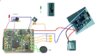
And while I was at it I experimented with the led color.
(L) Warm White included in the kit, (M) Red, (R) Cool White.
In person the color is much more noticeable. I decided to go with a red led.
View attachment 1019322
Do you have any info on the aux button solution detailed someplace? How to wire it and how its setup?
 

Your message may be considered spam for the following reasons:

If you wish to reply despite these issues, check the box below before replying.
Be aware that malicious compliance may result in more severe penalties.
Back
Top