Aliens M577APC Full size build discussion thread

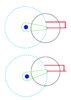
The drawing is just a scribble and only gives a very basic idea of the suspension, without showing key features which would explain the steering and braking systems fully.

The swing-arms main purpose is to act like the A-arms of an independent suspension. They allow the wheel to travel through a vertical arc as it moves over the terrain, and also contain the drivetrain. In the case of the swing-arms the drivetrain is double-roller chain (which is suprisingly affordable, used in the sawmill industry). They only control the camber of the wheel (sideways lean), the coilover-suspension controls the caster of the wheels (forward/backward lean) and supports the steering knuckle, outer hub and brake calipers (3 independent braking systems with two calipers each per wheel, for a total of 6 calipers per wheel).

Design history:
I was originally thinking hydraulic drive. Then i talked to Jon Kelley who knows more about hydraulic systems than i do and he said it would require large flow lines with high pressure to drive 4 wheels at any decent speed, and he suggested electric. He was thinking brushed motors but all modern systems are brushless and PWM. I found out that 4 brushless motors and controllers (for converting a car from gas to electric) were super expensive. As we are merely [cough, cough] movie fans and not a Government (whose elected officials think nothing is wrong with holding a convention in Alaska and using taxpayer money to feast on seafood imported from Norway), electric is not affordable. That forced me to design a mechanical-drive system, which is simply the diesel engine/transmission from a used delivery truck or ambulance feeding the intermediary axle and then the rear axle of a semi tractor.

As to the size of the vehicle, previous posters in this thread have expressed a desire to have one scaled Down to make the width 102" so it could be driven on public streets and highways (as the original was 10' 6" wide, not including the 11' 3" wide rear fenders). My opinion (worth exactly what you paid for it) is that having anything smaller than the original is just going to look like a toy. Even though it IS a toy, i would rather it look majestic or imposing. It would also be nice to have the interior big enough to use like the interior in the movie. If we alter the dimensions (for example making it taller so people can fit without making it wider) which i think would have convention fans constantly pointing out our mistake, and as i am not Dr. Who that means scaling it up so we can fit a full-size interior. The only affordable way to transport that size APC to and from events is to make it seperate down the middle so each half can be transported cheaply then reassembled near or at the event. If you want to drive it on roads for fun there are thousands of square miles of desert in the American southwest criscrossed by abandoned mining roads where no one will care what you do (just don't shoot any more holes in the Saguaro cactus).

I wish i could drop everything and build a 1/8 scale model right now, it would showcase the entire design and be easy to comprehend. And i do intend to build such a model as a prototype before starting on the full-size vehicle.

I will produce mechanical drawings tonight and post them to clear up any confusion.
 
Oddmar I realize it is just a scribble but you did kinda brag that you had the whole thing "designed". I'm just saying that seems like it's not the case.

My issues is not that I do not understand your drawing, I've seen worse. I realize what the part are suppose to do but thank you for your concern. I've played with a things you put petrolum products in a little over the years. I'm just trying to point out issues with the design especially the one concerning your chain drive and the travel of you wheel during compression of the suspension as these seem kinda like beard and butter to me and I'm certainly no expert. I realize you are not seeing what I mean and maybe I'm not explaining myself it but please don't waste your time trying to convince me. Use it building man. I'm just some guy on the internet who has already hijacked this thread too much from the OP. Sorry for that Rick H...
 
Oddmar -
I am eager to see how you intend to work out steering with your chain drive, and a prior commenter was correct - it's going to take a big honkin' chain to drive the thing (it's going to weigh rather more than a big Suburban, which is only about three or four tons, loaded.)

I'm still thinking that electric or hydraulic is the way to go on this, it's going to make steering - and splitting the body - a lot easier (and hydraulic will likely cost as much as your proposed chain drive, once we figure out what size chain will be needed, which will take figuring out a rough mass of the thing.)

Can anyone give me dimensioned drawings to work with? As I said, I "lost" my USCMTM (along with a load of other stuff) when I couldn't pay my storage bill (damn,) so I need something to work with. Once I know the size of the thing, I can start cranking out drawings, work on math, and start working out a rough weight of the thing (so I can then figure out the drive.)

Given what we've talked about, I'm inclined to think this thing is going to tip somewhere around 5-6 ton - scratch guess. So, someone please give me dimensioned drawings (the more detail, the better,) and if you can figure out what you want to do for the skin and figure a weight/square foot, we can really get started figuring this out.

I know what you're trying to do with your chain drive and swing arms, but this thing sits pretty low - so you're going to have trouble keeping your chain from dragging, with the low floor - you're not going to have much room for your differentials, and I can't see much room for the swing arms, either. I've been kicking around a modified A-arm-type suspension, something more compact that should fit in behind the wheel rather neatly (I'm figuring the wheels will be steel, yes? See if you can get a weight on that tyre you've found, so I can account for all of that. Since you've found a tyre you like, there's obviously a wheel for it, so it's a matter of finding that and finding a hub to fit it. I'll look up that tyre and see what I can find out, once I get a moment.)
 
Imagine a 50-year-old guy bouncing in his chair like a teenage girl who just found the Exact tire...!!


View attachment 1027656

The only problem with that tyre is that it's just under three feet in diameter. I've emailed them asking if they've got it - or they know of it - being about six foot in diameter, and if they can point us toward a wheel and hub for it as well. I'll let you know what I find out.
 
I don't tell people i can do something unless i Can do it. Most people don't have the time or patience to sit and listen to me tell them exactly what part, what supplier, how much, and exactly how i intend to bolt all that stuff together into a working, finished product. When i say i "have it designed", i don't usually mean i have it all drafted out on paper. I don't in this case. I can visualize mechanical parts exactly the same way someone would use a CAD program on a computer. I can 'see' the part, how it will interact with the ajacent parts, and can estimate what forces will be applied to it. I can rotate it and view it from any angle, then if i choose, 'look' at that view and reference it as i draw it on paper. Most of my designs are stored in my head and will perish with me when i have that unscheduled heart attack.

I'm just trying to point out issues with the design especially the one concerning your chain drive and the travel of you(r) wheel during compression of the suspension as these seem kinda like beard (bread) and butter to me and I'm certainly no expert.

I understand that you are trying to explain steering geometry to me even though my scribble only shows suspension arms. When i 'designed' the suspension/steering, it went something like this. I was presented with a constraint that none of the suspension/drivetrain components are visible in the interior shots in the movie. I remembered a large forklift i used in 1993? at a welding company in Sun Valley, CA that had the front wheels on either side of the forks. Since the forks were in the way there could be no conventional axle. I don't remember how the wheels were attached but i remember they were driven by chain from an axle just behind the fork assembly.
I thought of how the APC is shaped and visualized the swing-arms supporting the wheels and containing the chain-drive. They would 'straddle' the interior and the axle/drivetrain could be inside the floor. As i imagined them swinging up and down my 'creative mind' just "supplied" a simple mechanism for keeping the steering knuckle upright while allowing for suspension travel. This last part happened in the space of 15 seconds.
Imagine me sitting in a room designing things in my head, and some guy just walking in and handing me the solution on a sheet of paper. I don't know how else to explain/express the process.
It doesn't always work that way. Often i puzzle out an 'ok' way to do it but knowing the solution has issues i worry over the design for days. Maybe there are a group of gnomish engineers in the background working on a solution as i mow the lawn. But often only hours...sometimes days...sometimes months later a better design just 'pops!' into my head, usually when i'm taking a break and daydreaming.

I only have a crude draft on paper so far so here is how it works in just words. You can count them but there's probably a thousand so that's the same as a picture right? ;)
There is a spindle on the outer end of the axle tube. Bearings go on the spindle then a wheel hub. But instead of a wheel one of the swing-arms bolts on to the hub. The swing-arm is an oblong piece of 3/8" or 1/2"-thick steel with a 4" wide piece of bar stock welded around it's circumfrence, and probably a (double) frame of 2" tubing welded down the middle, spanning it's length between the sprockets to add torsional stiffness to the arm.
Then two double-sprockets with double-roller chain are placed into the swing arm. You have to put the chain onto the sprockets first as there isn't enough room between the sprocket and the outer 'rim' of the swing arm to put the chain on After you install the sprocket(s). The 10" drive sprocket has a splined hub which slides onto the splined drive-axle shaft protruding out into the cavity of the swing-arm, through a hole in the backing plate surrounded by the nuts holding the swing-arm onto the axle hub.
There is also a ring, maybe 4" diameter and 1" deep, welded on the backing plate of the swing arm. Into this ring you place a bearing assembly that the sprocket's hub rides inside...because the sprockets need to be supported by bearings inside the swing-arm while they are driven by, and driving, the drive-axles. The swing-arm cover-plate sports a similar ring to support the outer bearing.
The 20" driven sprocket is supported by the same style bearings. The cover plate is bolted on, then a heavy spindle bolts on to the cover plate, at the opposite end of the swing-arm, the end that will support the wheel. Onto this spindle go bearings and a hub. Onto THIS hub you bolt an assembly that connects to the coilover suspension.
In that suspension is a male-female telescoping tube assembly, crafted from heavy-wall tubing, that is connected to yet another hub that bolts to the tube frame at the top of the wheel-well. As the swing-arms move through their arc of vertical travel, this tube assembly holds the knuckle-hub upright, retaining the proper caster/camber angle as the swing-arms move.
Thereafter you install a splined drive-axle into the knuckle-hub, which slides through the spindle into the swing-arm and engages the splined hub of the driven sprocket. The knuckle-hub has heavy knuckle 'ears' welded on it top and bottom to contain the steering knuckle bearings. You install the knuckle-bearings then the steering knuckle. A driveshaft yoke in the drive axle allows the axle shaft to 'bend' to allow the wheel to steer, just as is found in most straight-front-axle 4x4 trucks. To the outer knuckle plate you bolt a bracket which will support the brake calipers followed by the final spindle. Onto the spindle you put bearings then the wheel hub. A brake rotor onto the wheel hub, then after brake-caliper installation eventually the wheel.

I swear Chaank this will be alot clearer after i get the exploded diagram done...lol.
 
Last edited:
The only problem with that tyre is that it's just under three feet in diameter. I've emailed them asking if they've got it - or they know of it - being about six foot in diameter, and if they can point us toward a wheel and hub for it as well. I'll let you know what I find out.

Those numbers they describe the tire with were specifically designed by engineers to confuse people.

That tire is 73" tall, 20" wide, is 32 ply, and weighs 900 lbs. I emailed them asking for the weight and even though i told them i was elated to find the exact perfect tread design, they emailed me back with a spec sheet of a tire with a tread design that is nothing like what we want. They quoted me a price of $2300 delivered even though i told them to save the cost of delivery i would drive to Texas to get them.

In frustration (Did they even READ my email?!!) I looked around the net and noticed it says 'General' on the sidewall. Replacing 'Titan' with 'General' i found a score of companies selling these tires USED, with prices ranging from $500 to rediculous. I actually prefer the look of an APC that has been to 7 planets and seen 15 engagements, where the tread has scars and gouges. Try Proven Parts in Riverside, CA or (different) halotires.com
 
I haven't read your whole reply, sorry man, I'm flat out but again, the issue is the chain and bump steer. Here's a quick sketch - The top shows your axl running directly through the middle of your interior. Here your chain lays as flat as possible just like how a four bar/ or four link suspension would work. See that forward and backwards travel? That's bad but it works in a four bar because the links are long therefore the travel radius minimizes forward/backwards travel as the suspension compresses/releases.

What you have is the bottom version. You have maximized this travel, the thing every car manufacturer works desperately to remove. If you manage to find a chain that can take this amount of load which I completely doubt, your bump steer alone would make driving impossible.

On another note, I think if you are not working with the OP on this I would suggest starting a new thread to discuss your version of the project. I think we've already hijacked this thread enough don't you
 

Attachments

  • wheel travel.jpg
    wheel travel.jpg
    138.7 KB · Views: 343
As the title says, there has been some discussion on a few threads with members looking for plans, referance materials, and about the possibility of actually building a 1:1 scale (full size Aliens APC.)
Aliens m577 apc
Aliens APC Plans
So I thought I would make a central thread here to get others ideas and views on if building a full scale APC would feasible, or could be scaled and built as a faithful representation.
Feel free to jump in.

Hmmm (@ Chaank) [Irritable reply deleted in the interest of whirled peas]

You keep telling me my design will suffer from bump-steer, i keep explaining my design trying to clear up any issue you may have.

But i dislike arguing with people and we really shouldn't on this thread...it's not CB radio after all...
"I'll come over to your house and kick your ass"..."Yeah, well you better bring some friends along..."

Please wait for the mechanical drawing and all will be explained.
 
It was a dark and stormy night...
So i went to Steak n Shake and drew the exploded diagram of the M577 suspension/steering components. Because they have nice clean white tables, food to munch on, coffee, placemats to draw on the back of, and good indirect lighting for picture-taking.
20190615_045309.jpg
 
hahaha classic, sorry I've missed these up-dates. Again, no offense intended man, no need to yourself all upset. I'm not arguing with anyone. Sorry if it comes across like that. I'll check this out later when I get a chance...
 
Ok, I had a quick read of your posts but I haven't found anything that tells me I'm wrong. First though, Let's discuss the rear axle. Forget about the front for a second as the rear is simpler for the moment. Did you understand my drawing? The red lines show upwards travel of your suspension. If your chain assembly is made to pivot, as shown in my drawing then you still have a wheel that will move forward and backwards during your travel. This is still bump steer. Unless you are using a system where your chain has tensioners and your sprockets can move towards and away from each or you chain drive housing stays in a fixed position, then I can't see how you can stop it. The only other thing I can think you might mean is that the chain drive and axle are pivoting like a normal axl would as a single unit but from what you have also said about having the complete interior, this would be an issue and mean you would end up with a tunnel in your floor. Like I said, I'm talking about the rear here for the moment but if this is the case then that gives you bigger problems in the front. I'm only working off what you have told us man.

I suspect this comment is from my suggestion that you start a new thread?

Hmmm (@ Chaank) [Irritable reply deleted in the interest of whirled peas]

I'll take it that that is mostly suppose to be a joke but if you wish to post an "irritable reply" you are more than welcome. I'm not one to get bent outa shape by accounts on the internet but if you are then be my guest. I'm only going by what you have explained after like I said, you bragging you had this all designed. I'm not sure I know of anyone who would say a few thoughts and some scribbles on napkins is a complete design when it comes to something of this weight and size. What you are talking about is building extremely heavy machinery, moving machinery and untold amounts of time and money invested. Have you spend much time on the RPF? Have you check out some 1:1 scratch builds that have been going on on here. Some are projects that essentially copy vehicles that have already been build quite a few time but still run into huge challenges and financial issues and they're being staffed by incredibly talented, dedicated builders. But, my suggestion of starting a new thread came more from your apparent position that the OP and the discussion up to the point where you chimed in was not what you were interested in and that you know a better way. Now, there is nothing wrong with that and if that is the case then it is time to leave the OP to discuss their project here and you to start drumming up connections, advice and research on your thread. I wasn't trying to be rude, if it came across like that then I apologize but it's always seemed to me that that is kinda polite and the way things typically work. If not I apologize, please pay no attention. However, it does seem like you are talking here about a project you are starting and going to build yourself or with your friends or help so isn't that still a new thread thing? It also sounds like you are days away from jumping on and getting this beast of yours up and running so please, document it for us. A new thread is the place to do it. From what I've seen, if the OP and other commenters here continue on their route which I think sounds like a doable and considered build then I suspect we'll be able to follow that on this thread.

I'm not sure where the agro is coming from man, you do you eh, don't worry about anyone else. I enjoy discussion and I love engineering. If that feels like arguing to you then I'm not sure what to say man but that's gotta suck doesn't it
 
Ok, I had a quick read of your posts but I haven't found anything that tells me I'm wrong. First though, Let's discuss the rear axle. Forget about the front for a second as the rear is simpler for the moment. Did you understand my drawing? The red lines show upwards travel of your suspension. If your chain assembly is made to pivot, as shown in my drawing then you still have a wheel that will move forward and backwards during your travel. This is still bump steer. Unless you are using a system where your chain has tensioners and your sprockets can move towards and away from each or you chain drive housing stays in a fixed position, then I can't see how you can stop it. The only other thing I can think you might mean is that the chain drive and axle are pivoting like a normal axl would as a single unit but from what you have also said about having the complete interior, this would be an issue and mean you would end up with a tunnel in your floor. Like I said, I'm talking about the rear here for the moment but if this is the case then that gives you bigger problems in the front. I'm only working off what you have told us man.

I suspect this comment is from my suggestion that you start a new thread?

Hmmm (@ Chaank) [Irritable reply deleted in the interest of whirled peas]

I'll take it that that is mostly suppose to be a joke but...

Yes, i try to joke alot to brighten the mood.

From what i understood Rick H was trying to start a 'central' thread where people could talk about the feasability of building a 1:1 scale M577 APC or something close. Not build one himself, necessarily. As we are still in the design phase this seems like the best place. I could start another thread if HE wants me to.

I thought you were being aggressive towards me, but if not, cool. Peas.

Still, you seem fixated on 'bump-steer'. On a normal vehicle, bump-steer happens when the suspension travels so much that the tie-rod (connected to a steering box mounted to the frame) pulls the wheel excessively. The angle of the rod increases shortening the apparent length of the rod, pulling the wheel out of position.

My wheel is steered by a hydraulic ram attached to a vertical telescoping sleeve. NOT the frame or chassis of the vehicle. The sleeve holds the steering knuckle upright as the swing-arm moves up and down. An optical encoder atop the knuckle bearing lets the steering system know the exact angle of each wheel. Yes, the steering knuckle Will tilt SLIGHTLY backwards, then forwards, as the swing-arm moves through it's Entire arc of travel, but very little. That would change the caster angle slightly. If you look at the drawing, that is, MY drawing not your own, you will see the steering knuckle is attached Not to the swing arm but to the rigid upright telescoping sleeve. There is a pivoting hub on the swing arm that isolates the swing-arm from the steering knuckle, forcing the steering knuckle to remain in an upright position as the swing-arm travels up and down.

The chain and sprockets are contained inside the swing-arm, which is a closed oblong steel container. The sprockets ride on bearings and don't move around. Splined drive-axles fit into the splined hub of the sprockets. There is some oil in there for lubrication, probably 80-90w.

The swing-arms are supported by a coil-over-shock suspension, connected to a hydraulic ram which varies the ride height. The swing-arm suspension doesn't SWING radically up and down as the vehicle drives over a regular road, the coil suspension has a normal range of travel, say, a foot or so. But if the terrain gets extreme, the hydraulics can lower or raise each coilover mount independently to try and keep the vehicle level. I didn't draw the variable-height hydraulic suspension system. The page was getting crowded so i only drew one coil spring and shock. But just from looking at the original (previous) drawing, one should realize the swing-arms wouldn't travel through their Entire range of motion just driving down the road.

I hope my explanation helps clear up any misconceptions about bump-steer.

My original steering design had a series of linkages and shafts, which went from the body, into the swing-arm just in front of the drive sprocket, twisting a rod which moved a tie rod at the driven-sprocket end, turning the steering knuckle. I was worried about bump-steer with this design so i came up with a better one.

If we go with hydraulic motors on each wheel as Jon Kelley is leaning towards, all the chain, sprockets, axles, transmission, etc will be unnecessary, simplifying things. I worry about the top speed of the APC if we go with hydraulic though. A nice feature would be true zero-turn, as we could toe-in the front wheels, toe-out the rear ones, and spin the APC around in it's own length. Like the Jeep Hurricane concept design...
 
Oddmar, I am stunned. I asked a few simple questions about my drawing and the rear wheels yet you are doing your best to avoid them. Judging from a few very small statements you included in your reply I suspect you are beginning to see I am right but don't want to see how dramatic the situation is. I'm not gonna waste any more time on this. Please PM if you want to reply otherwise I'll leave you too it
 
That tire is 73" tall, 20" wide, is 32 ply, and weighs 900 lbs. I emailed them asking for the weight and even though i told them i was elated to find the exact perfect tread design, they emailed me back with a spec sheet of a tire with a tread design that is nothing like what we want. They quoted me a price of $2300 delivered even though i told them to save the cost of delivery i would drive to Texas to get them.

Ah, okeh. 4x900# = 3600#, which should fit neatly in my 3/4-ton pickup, and give me an excuse to travel. Hmm... May have to check that CA source you cited.

The idea of doing a drive motor at each wheel is twofold:
1) As you want to have a longitudinal parting line (we've discussed this - it makes sense in theory, but the execution is something we're going to have to figure out...) we'll need an easy way to part the driveline side-to-side. Breaking an electrical cnx (quick-disconnect) or hydraulic line (dry-break cnx) will be a good deal easier than a spline coupling in a shaft, and having to "stagger" the shaft couplings so they can be lined up individually.
2) It will make it easier to rig steering. I don't think we can do a "zero-steer" setup a la the Hurricane concept (although I do like the idea, thought it was pretty cool when it came out. Also like GM's "Quadrasteer" that they had for a little while...) we'll have limited room for articulation of the tyres in steer, to maximise that we should steer all four of them. With the right valving, we can even "slip" or "dog-track" sidewise (turn both axles the same way to "slip," turn them in opposite directions to steer.)

We're still going to have to work out; A) how to support the centre of the thing when it's split (bloody great casters are the best idea here, and an example of a longitudinal driveline getting in the way yet again,) B) how to load/unload the thing from the buses (after modifying them,) and C) just how to slip those overlarge tyres sidewise to couple/decouple the two halves. (Oversize wheel dollies, as you see in body shops for moving vehicles about? Need a bloody huge jack to get them under the wheels, tho...)
 
I don't think we can do a "zero-steer" setup a la the Hurricane concept (although I do like the idea, thought it was pretty cool when it came out. Also like GM's "Quadrasteer" that they had for a little while...) we'll have limited room for articulation of the tyres in steer, to maximise that we should steer all four of them. With the right valving, we can even "slip" or "dog-track" sidewise

If we didn't have to make it screen-accurate, and didn't intend to drive it too fast, we could put mecanum wheels on it and drive sideways.
 
Hi people just found this thread by random on Pinterest, a good friend of mine was part of the original team which built the apc so if you want any information let me know cheers simon.
 
Hi people just found this thread by random on Pinterest, a good friend of mine was part of the original team which built the apc so if you want any information let me know cheers simon.
Do you know what became of it post filming?
 
Hi people just found this thread by random on Pinterest, a good friend of mine was part of the original team which built the apc so if you want any information let me know cheers simon.

You don't say? Don't suppose he still has any tech specs or prints lying about, does he? I would be unbelievably grateful (it would reduce what I'm working on to simple engineering, instead of design and engineering...)
 

Your message may be considered spam for the following reasons:

If you wish to reply despite these issues, check the box below before replying.
Be aware that malicious compliance may result in more severe penalties.
Back
Top