5 ft. ANH “Wooden” Falcon

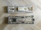
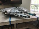
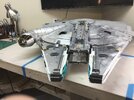
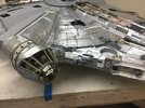
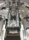
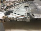
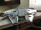
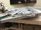
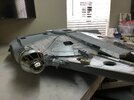
Update attached on progress made with armor plate. While this is .032 aluminum, due to my aircraft fetish, the thickness is about the same as styrene. Similarly easy to cut. Biggest amount of time is spent on measuring, segment line layout, notch location, nibbling correctly and, the all important kit part reference bench marks. I do not see how anyone can do this without templates and then some rework in order to get things relatively correct. Geometric shape cut outs on the front disc, so called 3” engine and radar pits, took a bit of work. Kit parts are still stuck on with gum rubber double sided artist‘s tape. All plates tacked on with super glue until I stop finding things that need fixing. Easy to pop them off at this time. I needed to measure the different sized & numerous large gaps between the plates and use jigs cut to the appropriate size width.

Those who opt for the 1/72 scale Bandai ANH Falcon can be assured that it is indeed perfect (in my opinion). The Japanese MUST have developed detailed drawings for their kit after getting Disney permission to use the studio scale model for reference. Drawings & dimensions made by the professionals on this site are awesomely accurate. That said, my bet is Bandai utilized the dimensions from the vintage kit parts and did some reverse engineering to dial the numbers in. It is logical since access to most manufacturers are in their back yard. The tiny 1/72 greeblies look identical compared to the kit parts when you hold both in your hand.

Back to work. This thing takes time.
 

Attachments

  • BE650A83-B7BB-4669-B4D5-89E7FC6EF9D7.jpeg
    BE650A83-B7BB-4669-B4D5-89E7FC6EF9D7.jpeg
    840.3 KB · Views: 212
  • 85662E5B-B262-46F7-B1A7-3E7FD6DF111C.jpeg
    85662E5B-B262-46F7-B1A7-3E7FD6DF111C.jpeg
    864.5 KB · Views: 203
  • 10C8E2B6-3858-49B6-823F-226B7AF18FF9.jpeg
    10C8E2B6-3858-49B6-823F-226B7AF18FF9.jpeg
    869.2 KB · Views: 222
  • B2026B24-B802-4902-AC2E-93CF5B4ECDB9.jpeg
    B2026B24-B802-4902-AC2E-93CF5B4ECDB9.jpeg
    886.8 KB · Views: 229
The Aluminum Falcon slowly transmogrifies... into the Alumilite Falcon, the Alumiplastic Falcon, the AlluMillennium Falcon!!!

It's looking GOOD. Amazing how the addition of just a few key greeblies transforms it from a steampunk vehicle into a studio scale replica. You seem to have nailed your armature dims, unlike myself...

Very much looking forward to watching the beautiful butterfly emerge from this aluminum chrysalis.
 
Quite the beautiful bird you have there Searun (y)(y) It would be a shame to paint it...but that's my taste of course;)
Yes, that AMF (Studio Kitbash started it:p) is a long build; eager to see your next update!!
 
Studio Kitbash,
Nice play on words for aluminum & Falcon. I continue to be taken to school on kit parts. The accuracy of Andre’s team work is demonstrated by the naked falcon drawings. A builder‘s careful measurement and construction is rewarded when the parts fit. A good example is the upper jaw box. Width fits the inboard mandible rails profile & the 1-1/4“ long Tamiya Centurion “bridge“ spans the gap to the turret edge.

Joberg,
Aluminum armor will eventually be painted since individually painting all greeblies up front before their installation does not seem practical. Kit Parts were not originally planned which drove the material choice. However, metal will provide a realistic base for weathering. Finishing this model is going to take a lot longer than I thought, but I am recognizing it will be worth the effort.
 
Attached is a picture of the upper and lower jaw boxes that have their armor installed. This permits the start of kit part location. It is a work in progress with some alignment necessary and practice on piping. I have tried to temporarily tack on those parts only when certain, as I can be, of their identification. Great appreciation of ILM for their application of greeblies and artistic skill. Lots of back and forth between kit part bags. Much to learn about cutting parts. One needs their “process” carefully thought out when doing this to avoid confusion. When all the parts start looking the same, it is time to stop and take a break. I am fortunate to have obtained kits parts from a knowledgeable source.
 

Attachments

  • 0A584832-AB07-4E47-8325-E8EED2A593C6.jpeg
    0A584832-AB07-4E47-8325-E8EED2A593C6.jpeg
    2.1 MB · Views: 137
Man, this is great workmanship for sure(y)(y)Would it be fun/different to paint the MF and letting some of its paneling bare, as to see the aluminium?;)
 
Man, this is great workmanship for sure(y)(y)Would it be fun/different to paint the MF and letting some of its paneling bare, as to see the aluminium?;)
Keen insight, that’s the plan joberg.

The build has already deviated from a strict Studio Scale with the present changes of aluminum armor, retractible landing gear and ramp, rotating cockpit and engine grill. Also, the fine details of the kit parts are so incredible, the painting technique may need to be thin washes to bring out the delicate features. Plus, I am afraid too much priming and air brush could could mask those greeblie details.
 
Fastened the removable cockpit tube, jaw boxes and mandibles on the disc. This provides some idea of how my project is shaping up. Excuse the tape and notes on yet to find pieces in the kit bags. Those structures are off when working.

Finished the armor on the bottom of the mandibles, so started applying kit parts when certain of their identification. Inboard greeblies were relatively easy. Focus is on Starboard Mandible outboard and top.

Lots of homework required to validate the tiny pieces in spite of maps, the many photographs and web page references. Foggy reference pictures, awkward perspective views, missing parts on the original, map differences, make small look alike parts quite challenging. Very rewarding when determined correct. While I do find the 1/72 perfect grade Bandai an excellent guide and kit instruction manuals valuable when part number is available, one can get easily lost in a reference “do loop” searching for multiple pieces. Even us left brain folks experience that difficulty.
 

Attachments

  • 7FBFFB69-4892-4118-8F1C-2563799E2C83.jpeg
    7FBFFB69-4892-4118-8F1C-2563799E2C83.jpeg
    1.8 MB · Views: 145
  • 3E11816A-BE00-438D-8F2D-13A16FD55A01.jpeg
    3E11816A-BE00-438D-8F2D-13A16FD55A01.jpeg
    1.7 MB · Views: 149
  • 04C308FD-B270-47DC-973B-B5EAE9957D1C.jpeg
    04C308FD-B270-47DC-973B-B5EAE9957D1C.jpeg
    1.6 MB · Views: 147
It's amazing to see how much it changes as you start adding the greeblies. It really transforms the model.

Great update!
 
It's amazing to see how much it changes as you start adding the greeblies. It really transforms the model.

Great update!

Thanks. The comment shows your experience in the art of the greeblie.

I was not expecting this change due to the model’s size and rather complex structure. Brand new to the kit part game.
 
Thanks. The comment shows your experience in the art of the greeblie.
Ha, NO,

Despite feverishly researching these things over the course of a few years, like yourself, I'm brand new to this art form also having yet to glue two pieces of styrene together in studio scale form.

I just recognise what looks good and I'm happy to say so in the hopes of encouraging more of the same!

Keep up the good work Searun!
 
She's looking so good Searun!. You can see the overall shape now in the pics & with the cockpit cone on she really does look the part!.
As you have said & are finding out now with dimensions & kit parts, correct fitment is a challenge & many hours of work studying & dry-fitting donor parts to match panel layout & subsections, it all takes time & much headscratching!.
But the kit parts on hand & good reference is key to a successful build, of which you are on track for i can see.
Thank you. I am just starting to recognize this. And, when I look at the work done by the “Master Builders“ on this site, appreciate the dedication this hobby choice takes.
 
Ha, NO,

Despite feverishly researching these things over the course of a few years, like yourself, I'm brand new to this art form also having yet to glue two pieces of styrene together in studio scale form.

I just recognise what looks good and I'm happy to say so in the hopes of encouraging more of the same!

Keep up the good work Searun!
A sign painter told me once told me that good lettering requires one to be able to recognize that the spaces between are as important as the lettering. Not that I have that skill. Copy I can however. Art Form is the perfect description. Your replies on this web site display your research to those that have gone down this rabbit hole.
 
Attached are some pictures showing the results of experimenting with piping technique on the upper jaw box, upper mandibles and forward disc quarter panels. Lots of adjustments needed. Must find some very small kit parts to replace temporary pipe fittings. Everything can readily be change be changed, and will need to be, when matching up with maintenance pit internal detail much later on.

For now, this shows what can be done with small copper & aluminum tubing. On the slightly larger tubing, one can insert solid rod into sections of the tubing to prevent “flat” bends. That rod can act as “pin” connectors when needed for extending pipe runs or adding 90 degree elbow turns. Serious studio scale folks will note I took some liberties by adding a few base plates. This keeps pipe slightly off skin surface (I can not run piping without pipe hangers, too many years in the power plant). Lots of chips added on the deck later will mask this personal engineering touch.

Forgive the tape and notes taken on the build.
 

Attachments

  • 237E9AC8-3C67-4EBD-B006-3B6545B2EEE2.jpeg
    237E9AC8-3C67-4EBD-B006-3B6545B2EEE2.jpeg
    2 MB · Views: 116
  • 503DB4D4-E17A-4A4C-89D5-9B4C656D43FB.jpeg
    503DB4D4-E17A-4A4C-89D5-9B4C656D43FB.jpeg
    1 MB · Views: 115
  • 6EF5A4A1-8820-443A-9AC0-66C95988C0A6.jpeg
    6EF5A4A1-8820-443A-9AC0-66C95988C0A6.jpeg
    2 MB · Views: 121

Your message may be considered spam for the following reasons:

If you wish to reply despite these issues, check the box below before replying.
Be aware that malicious compliance may result in more severe penalties.
Back
Top