3D Scratch Build - Battletech Argo

The gold in the screenshot, to me, looks like gold that has been around a while and wasn't polished. I would actually maybe tone down the paint a little. It's hard to tell without seeing it in person though.

My thoughts as well. But it also depends on which reference picture you take. Some are a dark old gold like above, others are more shiny but worn out gold. I am looking for something in between not too dark, but it should not look like it just left the factory either.

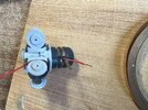
The picture of the pieces above was a coat of Revell gold directly on top of the primer coat (which has a nice sheen, but is not shiny... if you know what I mean), I gave it a wash of rust a couple days ago and they are looking better. There will be more washes before the job is done, so that "new-blatt-gold" look will definitely be toned down. Those pieces are the clamps on the round hinge to the habitat pods, and they are really small (all twelve of them fit on my thumbnail), so I wasn't worried too much about the shiny/not-shiny problem. Here they are with the first wash of rust:

Screenshot 2024-12-08 110543.png


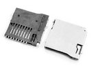
Below is the base for the left and right airlocks, just to show how easy it is to get a nice shine with Alclad chrome. Here the pieces are 3D-printed and painted (without sanding), first a base of Revell gloss black and then a coat of alclad chrome, and both coats with a simple paint brush. I did not want a mirrored finish, but if one was to make the effort to sand everything down with up to around 2000 grit and use an airbrush to apply the coats of paint, you can literally get a finish good enough to use for shaving yourself in the morning. :lol:

Screenshot 2024-12-08 110240.png

These pieces will get a final coat of Alcad candy ruby red... which I have to order yet, but at least in the internet pictures I have seen (especially here in Mark Baston's video), it is exactly the tone of red metallic that I was looking for. Not my work, but this is the color that I am aiming for:

1734797197458.png


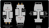
So here is everything dry-fitted together (the habitat pods are from an earlier test print and are not the actual pods that will be going on the model):


Screenshot 2024-12-08 110429.png


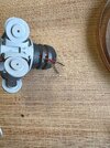
and here with the habitat pods folded back:

Screenshot 2024-12-08 110507.png
 
Last edited:
Just an informational sidetrack while I am waiting for the paint to dry. :p

The Argo was concepted for exploration and for long periods in space. Gravity is a luxury in the battletech universe (as our own), because humankind is not yet able to create gravity with technology (ala Star Trek / Star Wars, etc.), they relied on either Acceleration, Deceleration, or Centrifugal gravity. Centrifugal gravity is very expensive (needing a bigger ship and joints that can withstand the centrifugal stress), so even as today it is not in common usage.

Screenshot 2024-12-08 153412.png


Why is gravity necessary for humans in space? Deprived of the gravity of Earth, weight-bearing bones lose on average 1 to 1.5% of mineral density every month of spaceflight. Muscle mass is also lost much more rapidly under microgravity conditions than on Earth. In addition to these factors, during spaceflight, fluids in the human body can shift upwards putting pressure on the eyes that potentially lead to vision issues.


Fun fact: The problem with centrifugal gravity is that the spaceship / space station needs to be very big (much bigger than the Argo actually), to minimize the imbalance that occurs when the gravity at your feet is a different from the gravity at your head. Another downside of centrifugal gravity is that due to the direction of the turning, the sense of "down" is slightly angled depending on how high the rpm of the station is.

In essence, the bigger the station is (about a mile in diameter is a good starting point) the less rpm is needed and the difference in gravity layers does not cause ill effects. While researching for this model, I found a very interesting report on this from NASA and calculations for actually finding the best size for a rotating centrifugal ship that does not constantly nauseate the crew

Screenshot 2024-12-08 155643.png
 

Attachments

  • Screenshot 2024-12-08 153412.png
    Screenshot 2024-12-08 153412.png
    74.4 KB · Views: 36
Last edited:
Ok, I am really excited, I more or less, got exactly the gold finish that I was aiming for. It is a touch mirrored but you can just see a bit of the black undercoat, similar to those mirrors with the "aged gold" look. The uneven sanding also gives it a rougher look. The picture is not quite how it looks in real life, but close enough to give you an idea.

Screenshot 2024-12-08 230830.png


Also the second ring turned out very well. The ribs are much thinner, so the shiny gold aspect was not immensely important, but the two outer ribs are gold and the inner rib is polished metal. It was difficult keeping the middle rib clean but with a very steady hand and a lot of thinner anything is possible. :p

Screenshot 2024-12-08 230854.png


I also finished up the pieces for the habitat-pod-pivot mechanic. They will still get some weathering, so by far not the end product, but the stage is set.

Screenshot 2024-12-08 230941.png


Here they are dry-fitted on the centrifugal section:

Screenshot 2024-12-08 231016.png


And last but not least, here are a couple other odds and ends that got some color on them tonight. The cylinder-looking pieces are storage tanks for water, oxygen, or whatever. I have two versions, the first version from the first print (now for testing) and the second print in two pieces to allow access for lighting purposes. I hate to admit it, but I think in the 1-piece version, the coloring turned out a tad bit better.

Screenshot 2024-12-08 232930.png


[Edit] Hmmm, that picture is not the most current, I painted the gold similar to the pivot-mechanic pieces. I will swap the picture out for a new one tomorrow.
 
Last edited:
One heck of an update:cool::cool:(y)(y):love::love:

Thanks! It is amazing how much time goes into these little pieces that, once everything is put together, are only a fraction of the whole picture.

Here is a screen shot directly from the game, everything is so shadowed, but you can see the gold effect that I was trying to achieve. It took me a while to understand what it was, but the front gold ring has a gleam in the middle, due to two little "headlights".

Screenshot 2024-12-09 183901.png


I am not sure how I will drill the windows. No matter where you look they are all in perfectly straight rows, so nothing I will be able to eyeball. I have a miniature drill-press for my dremel, if I turn it to drill horizontally, all I need will be a kind of turn-table to turn the pieces and keep everything aligned.

Screenshot 2024-12-09 185945.png


On the nose, you can see that there are two openings on each side in the middle, as well as a larger round opening on the lower side. These are not in the in-game screenshot above. The Argo has two aerospace bays according to battletech specs, but they are never used in the game. Now this is a little bit of my own interpretation... As the Argo crash-landed on an airless moon and lay there for over 2 centuries, I am assuming that there just was not a priority to repair landing bays for a mercenary unit that had no aerospace fighters... the solution was to just quick and dirty patch up the bay door openings to ensure that the ship was space-worthy. After that, "out of sight, out of mind".

The larger round opening below the other two is not mentioned in any datasheets, but my interpretation is that this is a landing bay for larger shuttles and "repaired" in the same fashion. In fact, if you look closely, you can still see the very bottom of the circular opening behind the plate of steel covering it.

I have no idea what the producers at Harebrained Schemes were thinking of when they decided to do a last minute conceal of the bay doors, but the fact that they are there in the original designs but hastily covered up with scotch tape for the game, screams "Not now, but in the sequel you will get aerospace fighters!"

Now, my dilemma is that even though it is not exactly screen accurate... aesthetically, I like the Argo MUCH better with the bay doors, as opposed to the "nailed shut with a rickety 'closed for business' sign" version. I suppose I will settle for a theoretical version that we will never see, because a "part II" will never come. :(

This is how she looks when you first get her. The Argo taking off after 2 centuries of sleep...

mike-mccain-argo-0100-w.jpg

(Picture from ArtStation -Mike McCain)
 
Last edited:
It is hard to see the right color in this light, but they are more of a light copper as the gold on previous parts. And I gotta admit, these little guys are looking 10 different kinds of really nice...

Screenshot 2024-12-10 234433.png


These are the coolant fins that encircle the reactor section. On the concept designs you will see all 48 fins. It is not mentioned in any documentation, but the Argo flying in the game is missing some of the fins. It is kind of nice to see that someone not only put some serious thought into the damage one can have after crash-landing on a moon, but also the repair limitations of an engineering team on the go. I designed the reactor hull to fit all 48 fins, in case I ever want to do an "off-the-shelf" version, so I will have to putty-in the slots for the missing fins.

Screenshot 2024-12-10 235137.png
Screenshot 2024-12-11 102619.png


But can somebody tell me, whose bright idea it was to think painting all of these was a going to be fun?!?!?! :p

First pile primed front and then back, second pile coated with a copper base, and third pile steel grey finishing on the brackets and four tiny bolts... and the fourth pile that does not exist yet, will be to touch up where Mr. Butterfinger couldn't keep a steady hand.

Screenshot 2024-12-10 234533.png


I tried dry-fitting them in the reactor module slots... they fit but only with a bit of muscle-grease. I absolutely want it to be a tight fit, but these fins have literally the thickness of a business card and it feels like I am on the verge of breaking something when I am putting them in, so I will sand the tabs that insert into the reactor down by a hair.
 
Last edited:
For the coolant fins I have 3 different variations in mind concerning the metal grey brackets. I have not yet decided which I like better.

Here a picture from my 3d design, It is difficult to zoom in on the actual pieces to see a difference, but I will try to get a before and after picture up.

Screenshot 2024-12-11 164242.png


  1. Completely in Bare Metal Grey... The problem with this version is that the little screws next to the brackets are harder to see and optically almost merge into the brackets of the same color.

  2. Brackets in Bare Metal Grey, but only down to the base of the bracket... Although it is almost too much contrast, I like this version better as No. 1, but it just seems like something is missing

  3. Brackets in Bare Metal Grey down to a base in Gun Metal Grey... I like this the most, but the potential for un-straight painting lines is x3 of the other two versions.
Once I start weathering and applying washes, my opinion might change dramatically, so I created 3 test groups that I will wash and weather to see how the final product will look.

I know, somebody out there is thinking, "WHAT? but those details are so small, nobody will ever see a difference." [Smarty-pants mode ON] Yes, but the way I see it 'Perfection' is made up of many tiny little steps, besides... as Confucius said; "The path is the goal." So whether I take 10 steps or 20 steps to get there, it is the time from beginning to end that defines us. [Smarty-pants mode OFF] :)
 
Last edited:
It is hard to see the right color in this light, but they are more of a light copper as the gold on previous parts. And I gotta admit, these little guys are looking 10 different kinds of really nice...

View attachment 1887358

These are the coolant fins that encircle the reactor section. On the concept designs you will see all 48 fins. It is not mentioned in any documentation, but the Argo flying in the game is missing some of the fins. It is kind of nice to see that someone not only put some serious thought into the damage one can have after crash-landing on a moon, but also the repair limitations of an engineering team on the go. I designed the reactor hull to fit all 48 fins, in case I ever want to do an "off-the-shelf" version, so I will have to putty-in the slots for the missing fins.

View attachment 1887361 View attachment 1887438

But can somebody tell me, whose bright idea it was to think painting all of these was a going to be fun?!?!?! :p
First pile primed front and then back, second pile coated with a copper base, and third pile steel grey finishing on the brackets and four tiny bolts... and the fourth pile that does not exist yet, will be to touch up where Mr. Butterfinger couldn't keep a steady hand.

View attachment 1887359

I tried dry-fitting them in the reactor module slots... they fit but only with a bit of muscle-grease. I absolutely want it to be a tight fit, but these fins have literally the thickness of a business card and it feels like I am on the verge of breaking something when I am putting them in, so I will sand the tabs that insert into the reactor down by a hair.

Have you considered maybe just buying a sheet of brass and using it to make the panels?

What you have done 3D printing is gorgeous, but no print lines, no layers, no painting if you just broke out the dremel and cut the pieces.

Also, maybe just thin styrene could have made the pieces in a few hours with the templates. Sanded and painted.

And don't get me wrong, tbis project is WUNNERFUL, I played Battletech and Mechwarrior in the 1980s, just thinking out loud on some shortcuts.
 
Have you considered maybe just buying a sheet of brass and using it to make the panels?

What you have done 3D printing is gorgeous, but no print lines, no layers, no painting if you just broke out the dremel and cut the pieces.

Also, maybe just thin styrene could have made the pieces in a few hours with the templates. Sanded and painted.

Thanks for your thoughts. Yes, that did cross my mind, and generally that would be an option, but in my case, it wouldn't work as there are red lights at the tops of the fins and my idea is to let light travel through the inside of the (hopefully) transparent fin, to a spot at the top that is not light blocked. With my printer, you usually do not see any layer lines, but for some reason, if the surface is at exactly a 90 degree angle to the print bed, I get vertical lines (as opposed to horizontal layer lines that you often see in 3D prints). If I tilt the model just a couple degrees up or down, it is smooth as a baby's butt. As I printed these without sprues, there was no other option as to place them at a 90 degree angle.

I actually kind of like the texture on the fins... I am thinking ahead to the washes, that that should give it some nice characteristic. Besides, it kind of makes sense for the fins to have some sort of texture, after all their main function is to disperse heat (similar to a radiator) and the more surface space, the better the heat dispersal.

Screenshot 2024-12-11 102619.png


You can see the vertical lines quite well in the picture in the post before last. I printed them with Elegoo translucent (which was not very translucent in my opinion). In the meantime, I have printed a second batch using a transparent red (I think also from Elegoo but I am not sure). It did not turn out crystal clear as I had hoped, but definitely transparenter as the first attempt. The funny thing is that although it was the same print file, with the same settings, on the red transparent resin, there was almost no lining on the sides. I think I read somewhere that transparents need a bit more exposure time as normal resin, maybe that had something to do with it.

Aside from that, at least with my mediocre skill, I would say the chances are high that I would not be able to cut all the pieces so that in the end everything looks symmetrical. ;)

[Laugh] come to think of it... looking at the picture now, I could probably just cut up a bunch of pennies... That would REALLY give it characteristic! I'm sure the US government would get a kick out of that. :lol:
 
Last edited:
I have not had too much progress the last days to show, I have been busy hanging up the X-mas lights outside. Tomorrow the tree is on the schedule, but then I should have a little bit of piece and quiet. :)

Now that the Reactor Section pieces are coming along, this is the lighting plan:

1734195610952.png

There is not a lot going on light-wise, but the part that I have my fingers crossed for, are the little red lights on each fin. As mentioned above, I plan to print them in transparent and light-block everything but where the light is supposed to show. The success of this will largely depend on me printing clear enough parts. So far I have tried to print the coolant fins in translucent, but they were not translucent at all. For the next try, I used Red Transparent resin. These turned out much better, but I am still slightly skeptical it enough light can travel through to the tips. Working in my favor is that I want them to be very dim, but if that does not work, I will order a super clear Transparent and try it again.

The thruster bells, have pretty much the same concept, they will be completely light-blocked and with a white LED in the center. Another LED (yellow-ish to red-ish) will illuminate the backs of the bells (but light-blocked from the white), so that if I carefully sand the ridges, I should get a nice gradient shine-through so that it looks like the metal is heated up.

Other than that there are only two strobe Nav-lights (one on each of the little "wings"). They will be connected directly (through the central pipe) to the microchip in the Nose Section, so that the strobe effect does not get out of sync with the strobes on the front of the ship.

To test these parts I am going to have to pull out my circuitry and LEDs, which I have put off until now. I will be programming all of the blinking patterns on an arduino... and then exporting the whole arduino environment to an ATMEL atmega328P-PU chip and then wiring everything directly to the chip pins. This takes up the least amount of space and the chip itself costs only around 3 dollars.

1734196944855.png
1734199399697.png


In doing so I will also connect 5 pins (blue, red, black, green, and white connecting to the arduino in the picture below) from the atmega328P-PU chip to connection sockets mounted in the model wall (similar to the 5-pin socket above), giving me access to the microcontroller once the model is sealed up. That means years down the road, if I need to update the code on the chip I only need to connect the model to an arduino and upload the new code.

1734198745730.png

(Picture from Derek Malloy's video "Arduino on a Breadboard")

Speaking of years later. When I build a model, I usually collect a LOT of data, things like reference pictures, STL printing files, arduino code, and of course my build protocol. To make sure I will always have this data at hand if I need it, another trick that I like to incorporate in my models is mounting a spring loaded Micro SD Card Holder.

1734200738461.png

This is not wired to anything, it is simply mounted somewhere obscure on my model so that I can slip a micro SD card into into it and the card is flush with the surface of the model. If I ever need that data again, all I need to do is push the spring-loaded SD card (that has a copy of all the data on it), until it pops out and presto, everything is at hand.


Attachments

  • 1734199792514.png
    1734199792514.png
    67.6 KB · Views: 37
Last edited:
I am always not willing to see any other guys making a great model while I'm making my model. That makes me depressed as compared with my crappy craft.
But I can't resist to see this build.
Good work!

Hi Katsu-san, thank you for stopping by. Your modesty is completely unfounded, I am only doing the best I can with the little skill that I possess just to keep up with all the amazingly talented professionals in this forum.... and I include you in that group of individuals. :)

Well, I got the mandate from the boss that before I am allowed to put a finger on any of my stuff, there is another build awaiting my attention...

1734275314888.png


This old guy has been a part of the family for over 16 years now.
 
Last edited:
Now that the tree is up, I was released from all other duties. ;)

I used the opportunity to clean up the piles of electrical odds and ends that have gotten very spread out over the course of the last couple years and various projects. First thing to do was to create the slip-ring that on the centrifugal section for transferring power from the non-rotating pieces into the rotating pieces.

There are slip-rings out there that you can buy for quite cheap, but as I only need to get two wires over this boundary, and the form requirement is a bit too specific, I decided to design my own and incorporate the slip-ring into the centrifugal piece. The principle is actually quite simple:

Screenshot 2024-12-15 231630.png


Disclaimer: I am NOT an electrician and everything I have learned is by my own trial and error, so there may be better ways to do this.

The first step is to wrap a copper band along the bottom of the channel (here the power (+) channel)... From the adhesive copper band below, I cut about a third from the width, and it fit perfectly into the slot. Make certain to cut the length at about half of the circumference extra so that the copper band overlaps itself and ends exactly opposite from where you started. This will help you a great deal once you get to soldering. If the ends are too close, the hot iron will soften any solder already there and it will be almost impossible to keep everything in place.

IMG_2355.jpg


Next, thread the insulated wire through the holes. For this I am using 0.14mm wire. Depending on how tight the fit is do not forget to solder your wire tip now at the latest:

IMG_2357.jpg


After applying flux to the copper band, heat a layer of solder to the entire band, also making sure that the wire tip is solidly embedded in the solder, but to the side and not causing any large lumps. Remember flux is your best friend, use it amply and without reserve, any leftover can be cleaned up later. ;)

IMG_2358.jpg


And then the same again for the ground wire (-)

IMG_2359.jpg


IMG_2360.jpg


If the solder is shiny, it was a good job. If it is a dull matt grey, then the copper was likely not hot enough and chances are high that there is not a good contact.

I did a much better job soldering on the second wire as the first (typical), but for my purposes both are good enough. Assuming this will be turning for years and years, there will be wear on the parts and the copper band alone could get thin to the point that the connection is spotty over time. This is the reasoning behind giving everything a coat of solder, to give the construction a bit more mass. If I wanted to make it even more robust, I could have taken very thin strand of copper wire and wraped it around enough times to cover up everything. And then solder that layer to the copper band as well. In that case, the copper band would be optional and only there to keep everything in place until the solder sets.

I heat my soldering iron to just over 400 degrees C (that is about 750 degrees F), this would melt an injection kit piece without even making surface contact, but amazingly, the printed resin did not have any problems at all withstanding the heat. Even though it came into direct contact with the hot iron on multiple occasions.

Now the only thing left to do is to attach two metal arms to the inside of the nose, so that each lays in one of the channels, with just enough tension to keep contact while the slip-ring is turning. Important thing is that the two arms never come into contact with each other, as that would cause a short circuit and likely cause damage to the electrical chips. Best to do this with some kind of spring so that it is flexible, and yet applies continuous pressure.

Thanks for tuning in.

Jason
 

Attachments

  • IMG_2356.jpg
    IMG_2356.jpg
    2.5 MB · Views: 36
  • IMG_2357.jpg
    IMG_2357.jpg
    2.6 MB · Views: 39
Last edited:
Spagetti code

I will be documenting the electronics in this post. As coding is a lot of trial and error, I will be repeatedly updating this post with the current status.

As mentioned above, I will be programming on an Arduino and then exporting that code to an Atmel atmega328p-PU chip (which is the same microcontroller chip powering the Arduino). You can buy them for around $2 to $5, so they are not only much smaller but more inexpensive compared to putting an Arduino itself in a model. In the picture at the bottom of this post, the arduino is the circuit board in the red box. I will be using this until the program works like I want it to. At the top of the breadboard (same picture) you can see a long chip, this will be the actual atmega328 that will reside within the model once the working code is exported onto it. As I am restricted on the amount of wiring that can go into the habitat pods, there will be a smaller microcontroller (e.g. an ATtiny-xx) in at least one of the pods to control the lighting there independently from the main chip.

1734432161922.png

For those who have never worked with Arduino or microcontrollers, it is really quite simple. There are 2 or 3 other electrical components needed to run the arduino environment on the chip (Arduino on a breadboard), but other than that you have 14 Digital Pins (the pins with the yellow circle) that are perfect for blinking LEDs, on top of that, the ones labeled PWM also support dimming. That means that on these 6 pins you can define various brightness levels (great if you need a LED that fades in or out). If the LED is not meant to change its light level, you can dim LEDs manually by simply adding a larger rated resistor, but with PWM, you can do this in the code up, down and anywhere in between dynamically.

The 6 pins with the grey circles are for analog communication (everything other than binary on or off). Normally these are for sensor data input, for example if I had a light sensor and wanted some LEDs only to turn on at a certain light level. But these can also be redefined to control blinking of LEDs... so with one chip you can control up to 20 LED blinking patterns. If multiple LEDs share the same blinking pattern, you can connect up to 3 LEDs to each pin (4 LEDs connected to one pin will be too close to the max milliAmp pin has to offer). There are ways to extend the amount of LEDs and blinking patterns to a theoretical infinity by connecting LED controllers (e.g. my favorite the Texas Inst. TLC5940 chip), but I will not go into that here.

The LEDs and their function will be as follows:

Main Body Microcontroller

  • [DONE] Main Navigation Beacons - White (around 5000k) with a ON (1 seconds) OFF (3 seconds) located on each of the 4 winglets (2 front and 2 on the reactor)
  • [DONE] Docking Assistance 01 - White orientation lights (5000K) on the jumpship docking pad blinking ON (0.5 second) and OFF (1.5 second)
  • [DONE] Docking Assistance 02 - Red orientation lights on each of the 2 docking collars, which will Fade-ON (holding for 2 seconds) and Fade-OFF (staying off for 2 seconds)
  • [WIP] Hull Illumination - Incl. the "Headlights", Airlock Door illumination, and Designation illumination. Constant ON, but switchable with a push button.
  • [Constant ON] Hull Running Lights - Red (very dim) - Constant ON
  • [Constant ON] Habitat Pod Pivot Cavity Illumination - Red (only bright enough to light up the dark corners) - Constant ON
  • [Constant ON] Living Quarters - Windows lighted in warm white (about 3000k) - Constant ON
  • Living Quarters_X - Over longer periods of time >5 minutes, some of the living quarters will randomly turn ON or OFF
Habitat Pod Microcontroller
  • [DONE] Habitat Pod Beacon - White (5000k) with a double strobe 0.5 second ON / 0.5 second OFF / 0.5 second ON / 1.5 seconds OFF. These LEDs will be OFF if the habitat pods are folded back
  • [Constant ON] Habitat Pod Position Lights - Red (on the 90 degree axis to the pod beacons). Constant ON
Reactor Microcontroller
  • [WIP] Thruster flicker - White (Kelvin haven't decided yet) - very light flickering (MUCH less than a candle flicker). Each of the 3 thrusters has its own random pattern and do not flicker the same.
  • [WIP] Thruster Bell radiant heat - multiple LEDs (Yellow to Red) placed around the edges. each offset with Fade ON (random 0.5 to 1.5 seconds) Fade OFF (also random duration)
All LEDs that are "Constant ON" will be wired directly to power, because if there is no blinking, then there is no necessity to connect them to an arduino pin. I plan to have at least one pushbutton hidden but flush/recessed with the hull surface, to allow me to turn on/off some of the LED patterns.

Well, from all that I am still a long way away. :)

1734367859364.png
 
Last edited:
I updated a couple of the blinking patterns above, It is sometimes difficult to find the right measure between realistic blinking and a "Christmas tree on steroids" type of thing (read that term somewhere and loved it).

To keep the blinking symmetrical, all blinking patterns should fit into a 4 second cycle. I have the main Nav Beacon and the DoubleStrobe LEDs programmed, but the Fading LED for the airlock is being really illusive. I had a Fading script that I wanted to reuse, but it did not have the ability to stop for a duration at the highest or lowest brightness. Adding these two variables is proving to be a pain. :)

Although I have not tested them on the breadboard yet, I have old scripts for both the Thruster Flicker and the Thruster radiant heat, so it will only be a matter of changing the numbers to find the right flicker rate. The only difference between the two is that the Thruster radiant heat will need to be done with 3 LEDs flickering in sync with one another, and the Engine flicker is only one LED.

If any of you out there remember the monogram Galactica that I attempted back in 2011, the flicker effect will be an updated version of the same code.

This is the youtube channel that I uploaded it to, but I have not used the channel since. If I ever get my Pixelworks channel cleaned up I will have to move it over.


It is hard to tell the difference if it is a flicker or the camera is shaking... A little of both I guess, but this was my first attempt to get a dual color on an engine thruster. Here the inner color is a white LED and I believe I had a blue LED on the top and one on the bottom to get a blue halo around the white.
 
Last edited:
In essence, the bigger the station is (about a mile in diameter is a good starting point) the less rpm is needed and the difference in gravity layers does not cause ill effects.

View attachment 1886792
I would like to see nested rings—outermost..Earth Gravity…Venus…Mars..Moon…Ceres….hub.

Thin tubes with pictures on the bulkhead showing where you are gee-wise.

Astronauts could be in something like a railway car that can inch along from one ring to the next.

Like staged decompression…it helps with getting folks used to going back up to 1g.
 
I would like to see nested rings—outermost..Earth Gravity…Venus…Mars..Moon…Ceres….hub.

Exactly, as soon as you have a centrifugal produced gravity and multiple levels, you will automatically have the various G's. The closer you are to the central turning axis the less gravity you will experience... hence the problem with "too small" space stations where the gravity at your feet is a noticeable difference to that at your head. In my diagram above, the habitat pods only have 1G on the main living deck when the turning centrifugal is activated. In the game, the other decks with lower gravity are for things like the hydroponics garden, and a low G swimming pool for recreation.

Babylon 5 goes into this topic quite well, as they have species accustomed to a wide variety of gravities, the decks are organized according to their distance from the central turning axis (for the most part, some ephisodes contradict this, but hey, it is science fiction. :) ). Along the middle of the cylinder, where a 0G transportation system is located traveling the length of station.
 
Last edited:
For the radiant heat effect in the thruster bells, I need to order some new LEDs.
I have red, but I would like to combine that with an orange, and maybe a yellow as well. Because of the small space, I will need to work with SMD LEDs of the 603 variation:
1734872451587.png


I have used them before, it is not exactly easy to solder the wires to them, but not impossible. I will probably place them in a ring around the outer edge of the thruster bell, but I will need to do some tests to see which placement and fade pattern gives me the best results. Something like this... maybe...

1734892690368.png


[EDIT]: I am quickly running out of space in the reactor section. The radiant-effect on the thruster bells, will need a fading effect. Even with the constellation above, I will need at least 6 PWM capable pins for one thruster, and there are 3 thrusters. It looks as if I will neither have enough room in the reactor section for the microcontroller chip(s) nor will I have enough PWM pins on the arduino. The only other option is to control the fading patterns from the front of the ship, As I will be needing more PWM pins as an Arduino has to offer, I will most likely need to connect a Texas Inst. TLC5940 chip LED controller to give me more PWM pins.
 
Last edited:
Exactly, as soon as you have a centrifugal produced gravity and multiple levels, you will automatically have the various G's. The closer you are to the central turning axis the less gravity you will experience... hence the problem with "too small" space stations where the gravity at your feet is a noticeable difference to that at your head. In my diagram above, the habitat pods only have 1G on the main living deck when the turning centrifugal is activated. In the game, the other decks with lower gravity are for things like the hydroponics garden, and a low G swimming pool for recreation.

Babylon 5 goes into this topic quite well, as they have species accustomed to a wide variety of gravities, the decks are organized according to there distance from the central turning axis (for the most part, some ephisodes contradict this, but hey, it is science fiction. :) ). Along the middle of the cylinder, where a 0G transportation system is located traveling the length of station.

And remember the scene in Bablyon 5 with the bomb in the transport, where Sheridan appears to float, and has to be saved by a certain Vorlon.
 
Back
Top