3D Scratch Build - Battletech Argo

Pixelworks

Well-Known Member
Wow, has it been that long?

A couple years back, I got the new Battletech game from Harebrained Schemes. The game itself has its highlights and its downfalls, but is by far the best (at least at the time) mech piloting game out there. Being that I grew up with Battletech and D&D, there was really no question as to whether or not. :) The storyline was very interesting and I could really sink in to it. Somewhere down the line, the players must capture an old long forgotten dropship from a band of pirates. The Argo. The dropship had been marooned on a moon for about 2 centuries and getting her back up to standard specs takes most of the rest of the game.

For those who have never heard of battletech:
Battletech game - Theatrical Opening I never get tired of watching this. Shows Battletech history in fast-forward.

In short:
  1. Humankind expands into the stars, [centuries pass]
  2. a good Government grows/technology flourishes, [centuries pass]
  3. Government gets arrogant --> Civil war --> Government falls --> all the large houses are locked in battle for centuries trying to get the upper hand over the others. All the while technology begins to fade. --> Welcome to BattleTech.

vkOYkfBNVq_Q5tKU90BBZ23sq8gkhV7HYXv4vjssFu0.png

(Picture from ArtStation -Mike McCain)

I instantly loved the design. For those who remember their Mythology... In my defense, me being Jason, I probably could not have fought it even if I tried. ;) The design is quite unique in the battletech universe, but not so different that is looks out of place. HBS really did a great job in making it stand out. It is technically called a "dropship" but really only because battletech terminology just does not have a classification for such a ship. In all honesty, it is more of a miniature mobile spacestation if nothing else.

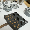
AT ANY RATE... The Argo and it's history were created solely for the video game but became cannon, so aside from in-game screen-shots there is not a lot of reference material out there. At the time of this writing, there are one or two STLs out there for download (likely in-game scans) but they contain quite a few errors and the proportions are distorted in some areas. I discarded the idea of using these for anything more than reference and built my own 3D model from scratch. In the end I have a full model that fits really well. At the moment I am in the process of chopping up the full 3D model into bite-sized pieces that my 3D printer can handle.

Screenshot 2024-11-22 001156.png


The Argo has 3 retractable pods that when extracted turn around the Argo's axis, creating artificial gravity for crew members. In the Battletech universe there isn't any gravity technology like in Star Wars/Star Trek, battletech ships produce gravity during either acceleration or deceleration, very few have a centerfugal gravity deck like the Argo. We are all so used to gravity just being a fact of life, that it is hard to imagine life without it. In addition to lighting her up, I do want to try to get the centerfugal rotation as well. I am not quite sure how that will work with electrical wiring but I will cross that bridge when I get to it.

mike-mccain-8ab6f3177109b4a12dc50e85cc6781cb-original.gif
mike-mccain-92b9f6e52a80dfd97e46f9b78005854c-original.gif

(Animated gifs from ArtStation -Mike McCain)

In my model, only the habitat section will be rotating. As nothing is completely frictionless, real-life physics would call for a opposite rotation to counteract the momentum... needless to say I will not be rotating the reactor section, as this would add a whole new dimension of complexity to the project.

According to Argo Specs - Sarna.net the "real-thing" is 320m long, when I am finished the model should be about 130mm so the scale should be somewhere around 1:2500.

Screenshot 2024-12-09 211242.png


A big Thank-you goes out to my reference sources:

Mike McCain - Concept artwork for the original for Harebrained Schemes. Hats off for this great ship. :)

Victoria Passariello - a very talented designer and worked on the original for Harebrained Schemes
Lee Schienbeim - 3D Renders for the Battletech Artbook.

Playing the game, I did not realize how big the Argo really is compared to other more known ships.

khmw666ansl71.png

(Picture from Reddit - toothpick95)

Thanks for checking in.

PS: I am not sure if it is only my browser, but for some reason there are a bunch of ad links popping up under the pictures and in the text. I did not enter them and I do not see them in edit mode to remove them. Sorry for any inconvenience.
 
Last edited:
Very cool! I love that game. It's a shame they will not get to do a sequel.

Last I read, HBS's license for Battletech had expired, so I doubt a part 2 will ever come, sadly. HBS is no longer under Paradox, so I imagine they are more worried about finding new investors. But, yes, the whole story just screams for a sequel. In fact, I actually did a short story that leads up to a sequel, The timeline itself offers a lot of opportunities, as the Restoration is placed about a decade or two before the begin of the Clan invasion.

Screenshot 2024-11-22 122223.png


I too loved the game. I have played it to the end and began over more times than I care to count, so this is in no way bashing, but, once you get to a certain point everything is too easy. Once you understood how the AI OpFor ticks, it was way too predictable and it could not adapt to player tactics. My A-Team lance could easily handle 5 waves and not even break a sweat, after that running out of ammunition was the only real worry.

Soooo... back to modeling. :)

I spent yesterday evening tearing apart the rear reactor section. As I mentioned above, I have to cut it up so that they fit onto the 130mm x 86mm print bed of my 3D Printer (an Elegoo Mars Pro 2 resin printer). Aside from that, cutting out pieces of the model will help me later when painting so that I have clean edges. The latter is especially necessary on the reactor, it is ringed by coolant fins, which would be a nightmare trying to paint them while attached to the body. So I will print them separately and attach them individually.

Screenshot 2024-11-22 093651.png


There will be a metal bar going through the entire model (the yellow rod in the picture above). This will give the entire model more stability and the centerfugal section with the 3 habitat pods will be attached directly to the rod with bearings. My current plan is to have the electronics in the front command section of the model. It will be tricky channeling the wires past the rotating section, but I do want to light up the engines, which is why everything here is hollowed out. Not sure if I can get it done at this scale, but if possible I will try to get a LED in each of the habitat pods to light up the windows, similar to how I wired the Babylon 5 station from the rotating to non-rotating sections.

I will be firing up my resin printer today and do some first tests if everything fits together the way it should.
 
Last edited:
The reactor section still needs some tweaking, I had a brain-fart in designing the coolant fins and need to go back to the drawing board on that. Nevertheless, I did want to have something I could put my hands on, so I finished up the front command section.

Screenshot 2024-11-23 140317.png


Only two pieces did not print properly (*cough* due to my not changing the support settings from my last print)... But after correcting the settings they printed just fine the second time around.

Screenshot 2024-11-23 142226.png
Screenshot 2024-11-23 142146.png


At the time I thought the center rod would be enough for alignment purposes, however, I should have made alignment pins on the hull pieces for additional support during assembly. I will have to make a mental note of that for the second time around. During the dry-fitting, I also realized that some of the interlocking pieces were calculated too close and they do not fit as I wanted them to... but nothing a little filing (a.k.a. the dremel) cannot correct.

I am printing everything on an Elegoo Mars Pro 2 resin printer and using white Elegoo water-washable (405nm) resin. The printer is not the newest model on the market anymore, but it still has a great resolution and is perfect for printing small pieces.
I use water washable resins in about 99% of all my prints, in fact the only time I use anything else is if I need a specific color that is not available in a water-washable variant. Beyond that, I try to use plant-based resin as much as possible, exceptions to that are basically also due to color availability.

Next step will be to sand everything down a bit and get some primer on these babies, which should really bring out the details.
 
Last edited:
Step by step. I finished the reactor shield section and the habitat pods today and got it printed.

Screenshot 2024-11-23 213052.png


Unfortunately, there was some contamination in the resin. I am not sure how it got there, the resin bottle is newly opened and the print bed etc. has been cleaned multiple times between prints. :unsure:

It did not do much harm, there are silver/grey flakes embedded in some of the pieces, which is not big thing, but some of the pieces did not print and the habitat pods stopped printing at about 90%.

Screenshot 2024-11-24 170622.png
Screenshot 2024-11-24 170732.png


For those of you who do not know the game, the little shuttle-looking ship is a Leopard-Class dropship that you start off with in the game. Once you "liberate" the Argo from the pirates, the Leopard docks on the docking collar on the side (as seen in the picture above in the first post) and is used to shuttle mechs to and from planet-side. I will be embedding a magnet on the underside so that the Leopard can be mounted on the Argo or removed if needed.

I cannot take credit for the Leopard though, I downloaded it from one of the STL sites a while back. Unfortunately, I do not remember who the creator is, but the design is one of the very best out there in the category "download for free". A big thanks from my side.

Thanks for tuning in.
 
Last edited:
Just a quick update before I turn in for the night.
Everything is primed with a coat of dark grey and then sprayed with a rough coat of light grey. The plan was to give the gold rings an additional coat of Alclad II Gloss black.... until I opened the bottle to find that it had turned to a consistence similar to mixture between jell-o and slime. Tomorrow I will see if I can thin it back to its original form.

Otherwise, this is impatient me doing a balancing act (on my totally compliant painting booth)... :p

Screenshot 2024-11-24 213701.png
 
Last edited:
For everyone who has read my threads in the past, they know that I cannot make a model without a lighting plan. :)

Screenshot 2024-11-25 133152.png


There is a lot going on light-wise, but you do not really see them in the overall look due to the low brightness. I will be keeping this in mind, and set most of these LEDs to something around 25% or even less so that they are visible but only barely. I also want to keep the lights small so as not to destroy the scale, the windows will be slightly bigger, but for the rest it will be done with either 0.5mm or .25mm fiberoptic strands. In addition there are a couple lights that are not in the original design, (navigation blinkers on the thrusters, airlock door lighting, and of course ship designation lighting)... think of them as "artistic-interpretation". :p

A microcontroller (an ATmega installed with an Arduino environment) will be located in the front command section and will be responsible for all the various blinking patterns and light levels.

As the habitation pods are pivoting and the centrifugal section that they are attached to is turning, there will be quite a few challenges in getting light to the spots where it is needed. The problem children are as follows:

Centrifugal Section – Due to the rotation, a current-differential or slip-ring will be needed to transfer power from the non-moving section to the moving section. Additionally, the centrifugal section is not very massive and needs to retain as much mass as possible for stability reasons. Because of this, the section cannot be hollow and wires/fiberoptic will need to be laid in channels and filled in using putty.

Habitat Pods – Lighting of the habitat pods is dependent on getting current over the centrifugal section. Once that is given, use a hollow syringe needle for attaching the pod to the centrifugal section and two lacquered copper wires can be channeled through the pivoting axis into the pod. In the pod itself, use an ATtiny in each pod to power the LEDs and control the blinking pattern… this may lead to a non-synchronous blink pattern between the three pods, but the only other option would be to daisy-chain a wire out of the first pod into the second and on to the third (#not-amused).

Habitat Pod Storage Tanks – Each tank has two red lights, one on the left and one on the right.
OPTION A: would be to hollow the tank out and cut it in half for access, leaving the free-hanging gold apparatus printable.
OPTION B: print the tanks with translucent resin and channel light in from the centrifugal section through the attachment arm. Both options have the additional dependency on how and if the centrifugal section is lit up

Reactor Section – It should not be too difficult to route two lacquered copper wires along the metal central spine of the ship (bypassing the bearings on the non-moving side).
OPTION A: As the only blinking that needs to be synchronous with the rest of the ship are the two navigation lights on each of the thrusters, it may be possible to route another pair of wires (total of four) lacquered copper wires (two for +/- current and two from the microcontroller for nav-light blinking.
OPTION B: omit two of the four wires from option A and use an ATtiny to control the blinking pattern of the navigation light in the thrusters. This can however lead to a non-synchronous blink pattern between the reactor section and the rest of the ship

Reactor Fins - The reactor fins (every second large fin) seem to have a red rectangle on both the front and the back and on both left & right sides. About the only feasible way to do this is to print the fins translucent and light-block everything but these light spots, lighting them from a LED located in the central reactor cavity.

Airlock Lighting – This is not in the original lighting, but for my tastes a "must-have". At any rate it might be difficult to route a fiberoptic strand through the other three pieces and then get the <90° angle needed to light up the airlock door properly... and not to forget that it is planed to have a magnet embedded under the surface for reasons of docking/undocking the Leopard.

Ship Designation Lighting – This is also not in the original lighting, but the Trekkie in me cannot have it any other way.
OPTION A: This will be difficult as the fiberoptic strand (or worst case a SMD LED, if the strand does not provide enough light) needs to be placed as far outward as possible with a <90° angle (recessed if possible) to light up the surface but as little as possible of anything else. Placement should be in the gold ring, probably in a carved channel that is smoothed out with putty afterwards.
OPTION B: I am not a fan of backlighting through the resin, but there may not be any other alternative. Needless to say that the hull needs to be printed in white resin for this to work.
 
Last edited:
The bearings arrived today and fit perfectly.

They are 693ZZ bearings and are the same form factor as the bearings in inline skates, only much smaller. They have a diameter of 8mm and are 4mm high with a hole of 3mm. I bought a pack of 10 on Amazon for 5.50€

[Edit]: My metal rod is also 3mm, it fits snugly in the bearing hole, but not tight enough to keep it permanently in place. I will have to find a way to make sure it does not move with time.

Screenshot 2024-11-26 150915.png


They are only partially in, as I still need to do some work on getting all the wiring done and the fit is so snug that once pressed in I will likely never get them back out again. ;)

Screenshot 2024-11-26 151009.png

Screenshot 2024-11-26 151101.png
 
Last edited:
The more I thought about it the less I liked the idea of the blinking among the three habitat pods getting out of sync. On top of that, I will need a slip-ring to transfer the current from the non-moving part to the moving and that would be much more stable if integrated into the centrifugal section itself.... *sigh* Soooo I went back to the drawing board and adjusted it to fit:

Screenshot 2024-11-26 221038.png


The slip-ring (the dark grey part in front) will go through the wall of and extend into the front command section so I will have more than enough room to work with. There the blue (+) and red (-) current will be wired into the turning centrifugal part. The small grey transparent cylinders will be syringe needles holding the habitat pods in place and allowing them to fold in and out. The needles themselves will be stationary (otherwise the wiring could be damaged) and the pod will just turn on their axis. Why syringe needles you may be asking yourself, well, first off I do not believe there are metal tubes out there in this size and if there were, they would probably cost much more than a pack of needles. As the needles are for medical, they are extremely strong for their size and although they may bend, they will never break... again because of obvious medical reasons. the only downside is that needles generally are not longer than three or four inches.

I know that sounds crazy, but I have already done the needles (without wiring) on a much smaller version of this and it works great. As the needles are hollow, there should be enough room to squeeze the (+) line, the (-) line, and a signal line that controls the blinking through and exit in the middle into the inside of the habitat pod.

Not shown above, but of course the red and blue lines will also have to go to each of the other habitat pods for the non-blinking LEDs. Once the wires are in the slots and everything works, I will fill in all of the recesses with putty so that everything looks nice and the wiring cannot catch on anything.
 
Last edited:
Had a bit of a setback today. The last couple of projects using my airbrush, I noticed slight problems with airflow. At the time, I assumed it was the airbrush, either a better cleaning needed or a defect rubber gasket somewhere. But in the end, everything still worked, so adhering to the principle "never touch a running system", I gave it a cleaning, and quickly put it out of my mind.

Wanting to sit down and make some progress today, I noticed there was pressure, but gone again after one press of the button. This was pressure in the hose, so the blockage could only be in the compressor itself. I have an AS-196 double valve compressor which I bought about a hundred years ago for around 150€, so not a high-end article... In the end the air-outlet from the waterfilter is stuffed with rubber. I am not sure if it supposed to be there, just in another form but it is the culprit I was looking for. It lets air through, but only at a fraction.


Screenshot 2024-11-28 131513.png


The metal screw is so tight (probably with lock-tight) that I cannot unscrew it no matter what I try. And I do not want to try to pry the rubber out as: a) it was probably somewhere in there for a purpose, and b) I most certainly do not want any debris making their way to my airbrush. Luckily, the whole regulator/filter assembly is not that expensive to replace, but it will be a practice in patience the next couple days.
 

Attachments

  • Screenshot 2024-11-28 131513.png
    Screenshot 2024-11-28 131513.png
    876.3 KB · Views: 49
Last edited:
Wow...love the way you're engineering all of those pieces/details together. :cool::cool::love::love::notworthy::notworthy:

Thanks! But believe me, I am about as far away from a professional designer as you can get. :)

I think it is just amazing the shapes you can create only using simple shapes (cube, cylinder, ball, etc.) or their negative. In the past I tried to learn how to use Blender.... I was lost like a 3-year-old in downtown New York, and have not even thought about trying since. I do 99% of all my work at Tinkercad.com, which has the main downside that too complex/large designs can time-out and are practically not downloadable... on very rare occasions I do use Mesh Mixer or Meshlab, but only as a crutch when Tinkercad is being fidgety. I am sure if I was better in one of those tools I could probably do things better/faster, but due to the required learning curve, I just have not managed to make the change.
 
Back after a X-mas party at work (and a day or two to recover).

Due to the changes to the centrifugal section, I had to adjust almost all of the other nose parts. It wasn't fun, but the work was necessary and it also gave me a reason to go back and make some other improvements that I discovered along the way... like better alignment tabs for putting the pieces together. Especially the rear part of the nose section needed an overhaul to allow room for the slip-ring that is now to extend into the nose section. There is a large opening in the back and the structural support needed to be "stretched" towards the front:


Screenshot 2024-12-02 003045.png


The prints so far will not be a loss, I will keep them and build a non-lighted (or less-lighted) version, just so that I have a piece to test painting/weathering ideas on.
 
Last edited:
I finished upgrading most of the parts, only the reactor section needs to be completed (due to the fact that I am dreading the effort needed to undo & redo)

The supply tanks (below) turned out really nice, it is hard to see in both the design and the print but the gold ring is actually only attached on the ends... the resolution of 3D printing never ceases to amaze me. :)


I printed the next batch with the new updates and everything printed well

Screenshot 2024-12-05 140902.png


I coated the new pieces in anthrazit grey primer and dry-fitted some of the parts.

Screenshot 2024-12-05 141036.png


I am still waiting for the replacement parts for my airbrush compressor, so I will be concentrating on the electrical aspects in the meantime. Nothing dramatic, but the arduino programming will not write itself. :p For filming purposes, the model will have a mounting point in the front and one in the rear, but I still need to decide on which connection to use for power.

I also drilled the needed channels in the centrifugal section. I was a bit skeptical in the beginning but it looks as if all of the planed lights in that section are doable. Also the rod that acts as a spine for everything (above) is hollow, with a inner diameter of 2mm I should not have any problems routing cables from front to rear past the turning centrifugal section. I love it when a plan comes together.
 
Last edited:
The gold pieces on the Argo are partially shiny. I have been trying different paints but have yet to find that perfect mirrored gold look. I have used Alclad chrome with a base of Alclad gloss black really successfully in the past and was kind of hoping to get something similar (only dirtier and a bit scuffed up). As I could not find any Alclad gold, I bought a bottle of AK Gold from the Extreme Metal Paints collection.

Screenshot 2024-12-05 150706.png


In the bottle, it looks and behaves exactly like the Alclad chrome (i.e. watery with swimming metal flakes), but I have yet to get a shiny finish. It seems to be very aggressive if painted on top of other gloss black paints. I tried a with a base of Alclad gloss black and Revell gloss black enamel. Both bases wrinkled-up in places once a coat of AK Gold was applied, but even then, the gold was more of a dull matt gold at best. I even tried a coat of alclad gloss black, then a coat of alclad chrome buffed up to an almost mirror finish and tried putting AK Gold on top of that... unfortunately with the same bad results.

I believe AK Gold is a lacquer paint (like Alclad), so it may have a problem with the enamel base from Revell and as for the Alclad gloss black, it should have worked as Alclad is also lacquer, but as my bottle "turned-bad", I tried using what little was usable, but that may have caused the unforeseen reaction. All-in-all, I have given up on getting that glossy gold "C3PO" finish and will have to settle for a normal matte/sheen for now.

Screenshot 2024-12-05 172900.png
 

Attachments

  • Screenshot 2024-12-05 172900.png
    Screenshot 2024-12-05 172900.png
    810.5 KB · Views: 49
Last edited:
The parts are really sharp and looking great:cool::cool:(y)(y) You're right about the gold paint; I've never had a successful result with gold.
It's a paint I dread to apply on any medium:((n)(n)
 
The parts are really sharp and looking great:cool::cool:(y)(y) You're right about the gold paint; I've never had a successful result with gold.
It's a paint I dread to apply on any medium:((n)(n)

Thanks. I will take some pictures of the failed attempts later this evening. It is a shame actually, with Alclad chrome it is sooo easy to get a really nice mirrored finish, before I started this, I thought, "How hard can it be?".

I am lucky that this model does not really call for a completely mirrored gloss, nevertheless, it should be mirrored and then dirtied down from there. With this matt gold, I can give it a wash but it will never have that "I used to be shiny" look. :(

Alright, I have really been pushing off redoing the reactor section.... but I sat down today and tore everything apart. The reason is that the fins themselves were simply embedded in the hull in the original version... as I will be printing them separately, they need to have a means of attachment that keeps everything symmetrical.

As I thought, it was a pain in the backside, but in the end I am happy with the results.

Screenshot 2024-12-06 153707.png


The fins extend all the way into the Interior of the hull, because I will be printing everything in transparent resin and light from the inside needs to travel through the fins to the red lights on their tips. To do this I will mask off the areas of light and spray the rest with metallic aluminum paint (rattle-can with real aluminum particles in the paint). I have found that this is a great light blocker and use it very often to spray the insides of models that need to contain the light.

For anyone who is wondering, there are a total of 48 fins (each with an offset angle of 7.5 degrees to its neighbor)... Masking each with 4 little squares for light sources is gonna be very exciting. :rolleyes:
 
Last edited:
So here they are on their way to the printer... now I have about 3 hours to drink a coffee. :lol: This batch will not be printed in white like the previous parts, but instead transparent/translucent.

The diamond-things on the top are not for the Argo. My son plays Ark: Survival Evolved on the playstation and has been begging me to make a supply drop for him for ages, but as I do not print in transparent that often, it has been waiting in the queue until now.

The fins I mentioned above as to why they need to be transparent, but also the reactor hull has some lighting going on that is just easier to let it shine through.

Screenshot 2024-12-06 180650.png


The thruster cowls will be printed transparent because in the past I have always wanted to try something on the thruster cowls of various other spaceships, and this time I thought that it is now or never. I will put a bright white LED in the center to depict the main thrust, but I want to give the metal a look as if various edges inside the cowl are heating up with a redish-orange light, kind of similar to this:

a4957160-216-Afterburner-RC-Jet-6.jpg
 
Last edited:
Great update:cool::cool:(y)(y) As for the gold, short of using real gold leaves to apply directly to your little parts, I don't see a great solution to obtain a nice glossy/gold look.:(
 
The gold in the screenshot, to me, looks like gold that has been around a while and wasn't polished. I would actually maybe tone down the paint a little. It's hard to tell without seeing it in person though.
 
Back
Top