2005 'War of the Worlds' Tripod from Pegasus - WIP

blipper

Sr Member
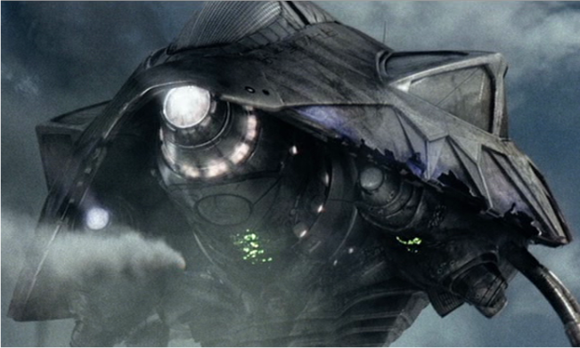
The film might have been quite the disappointment (though there were some strong moments) but I did love the way the tripods were handled - in design, motion and presence.

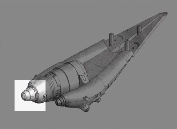
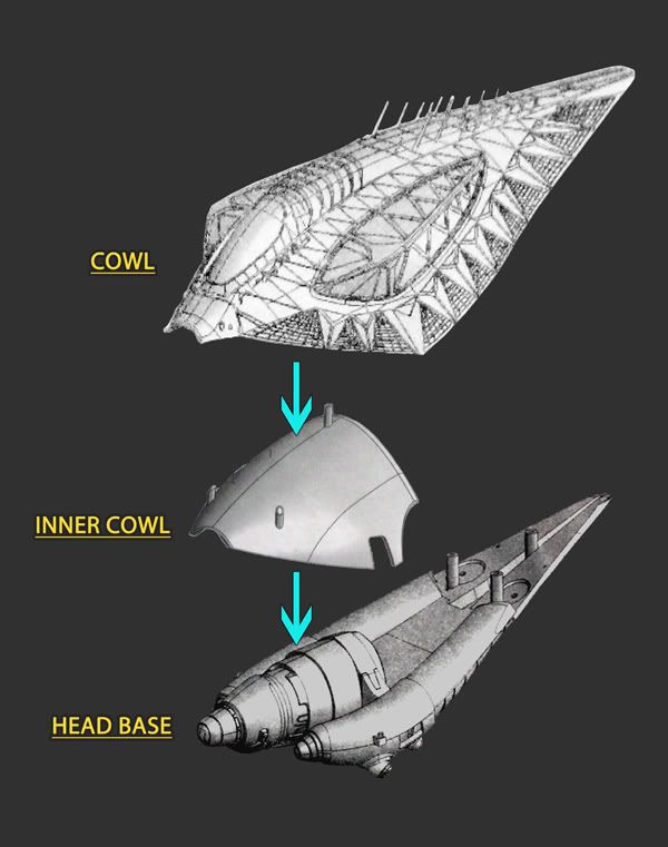
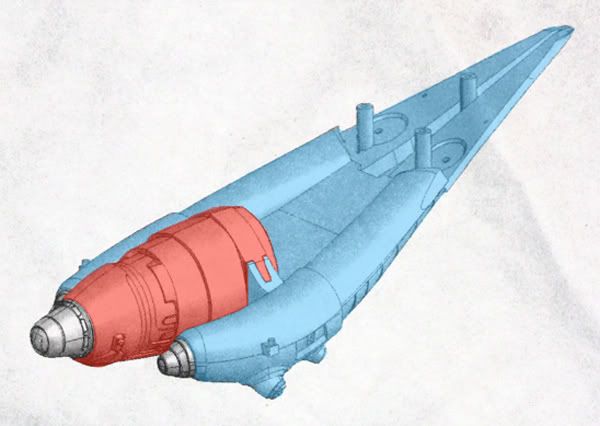
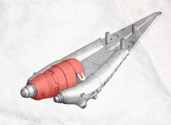
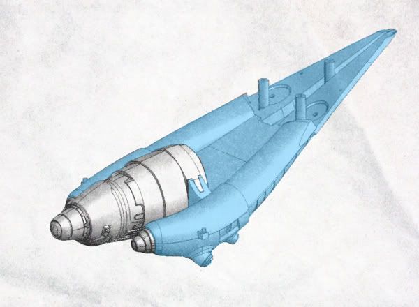
I'll accompany the area I worked on with a diagram from the instructions to illustrate the particular section. The diagram features the model in a mostly assembled state but it gets the info across.

First thing was the idea that I wanted to be able to assemble/disassemble the model where possible, for ease of painting purposes as well as any future storage.

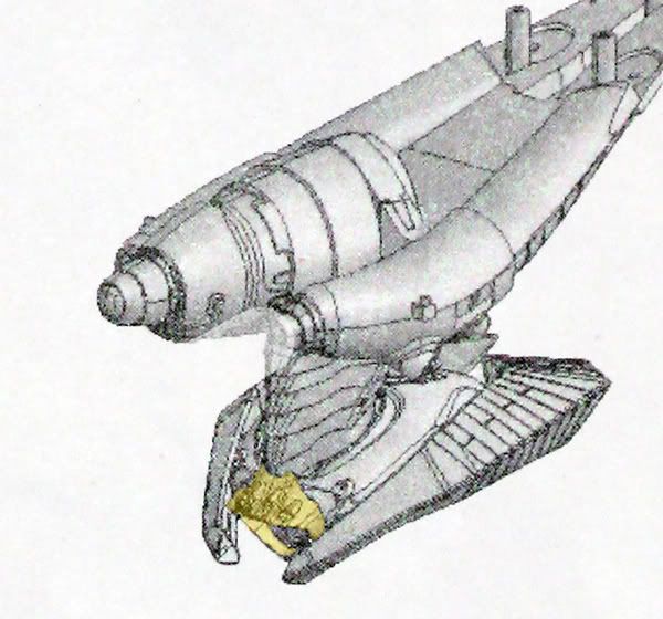
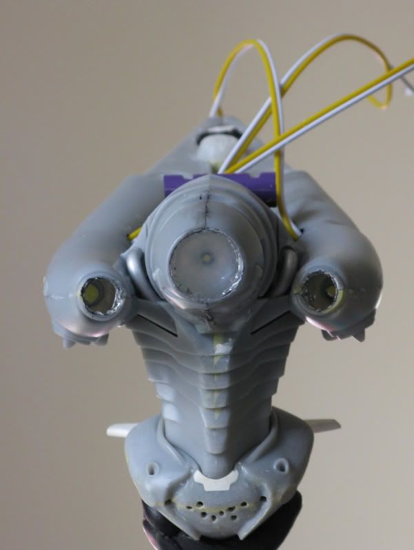
1 - NECK + BODY CONNECTION

01.jpg


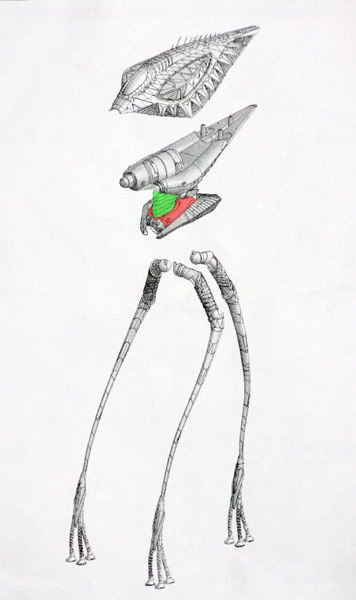
One immediate place seemed to be the neck and body, so using a couple of brass tubes, one which fit snugly in the other I went ahead.

02.jpg


03.jpg


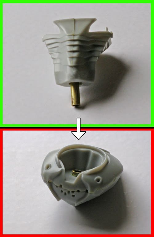
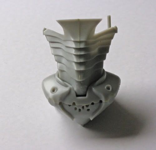
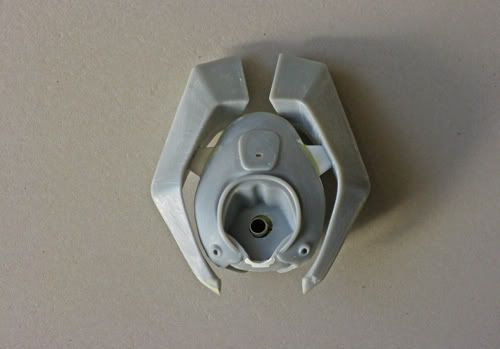
You might notice a pin on the right side at the top is lacking a twin on the other side - must have snapped off at some point but it's not a big deal and is more of a guide pin than a support.

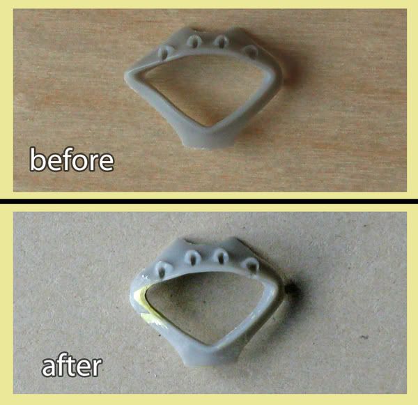
I've also shaved the bottom front of the neck of a little material as when the body 'tentacle ring shield' is eventually attached to the body front it would have prevented the neck and body from being easily assembled and disassembled. You won't notice this on the final model though as the shaved area is out of view behind a section of the shield piece and an area on the body to be filled.


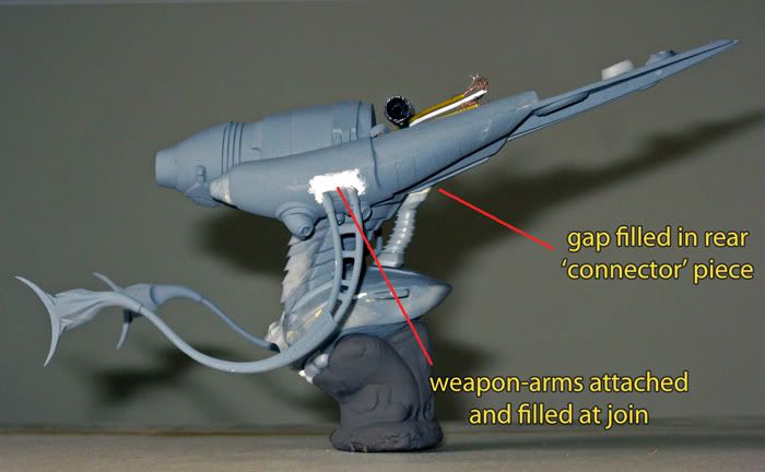
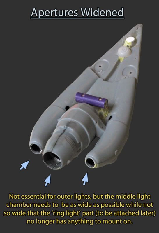
2 - BODY + APPENDAGES

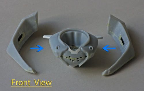
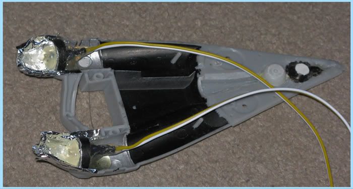
Next is the body and side appendages (not sure what they're supposed to be)

04.jpg


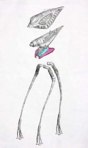
You are meant to use the pins to slot the appendages into the body but the alignment is very poor. It is possible to get them in but they are under a lot of stress and seem pretty fragile and I could imagine something happening at some point which could cause them to fly off.

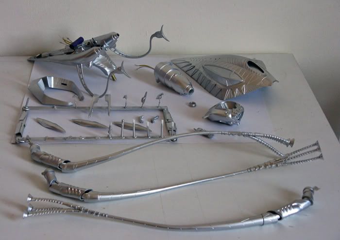
Here's one appendage side with it's original pins, or should I say 'pin' - yep one pin died in the process of test fitting.
05.jpg


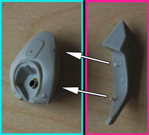
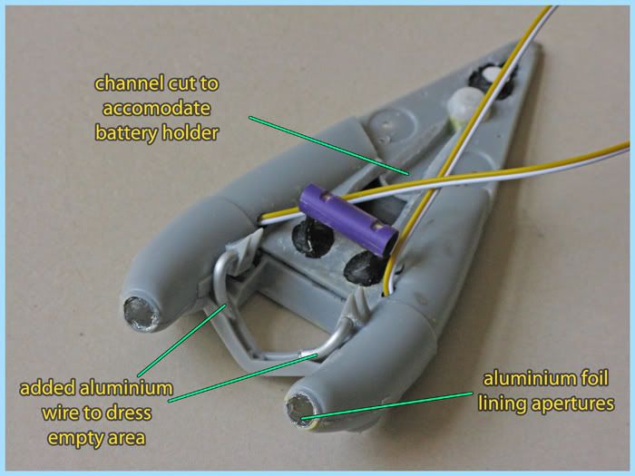
So I opted for a more secure fix and created a single strut support. Also a little milliput filling here and there.

04a1.jpg


04b1.jpg


04c1.jpg


04d1.jpg


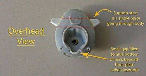
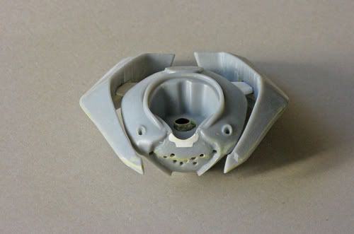
These appendages can now slot on or off which will be handy.

I must confess though that in my excitement at receiving this at Christmas, knowing I wouldn't be able to work on it for a while, I felt I had to glue something, anything together and feeling the appendage pieces (comprised of two halves for each piece) were a safe bet I super-glued them. When it came to actually working on those areas and modifying to a strut support I realised it was a mistake as I really wanted access inside each appendage piece. I managed to separate the joined pieces but it did create some damage - so excuse any random filler you see on each appendage necessary to get them back to spec.
 
Last edited:
Awesome.
I was thinking about working on this kit next after I finish my current project.
I love that you are detailing your build and I will be watching closely ( I may borrow a few ideas if you don't mind ).

I'm not sure if I missed it but do you plan on lighting it?
 
Thanks Danikin and certainly feel free to crib or dismiss anything in the build. The kit is pretty good straight out of the box but it's hard not to let some things get your attention, and judging by your excellent and thorough AT-AT build I can imagine there's some areas that you won't be able to resist -certainly there's a lot of seam filling and cleaning that requires work.

As for lighting, yes I'm lighting it, but I'll only go as far as the three forward lights. This is for a few reasons:

It'll be my first attempt to light a kit (A long while back I remember buying a bunch of grain of wheat bulbs for a Falcon - it didn't turn out to well and the idea of sealing in bulbs with a short life didn't really enthuse me. But with current LEDs it would be a shame to not give this great tripod kit something it seems to cry out for.

I'm not sure I could do that great a job on the translucent cowl/lighting, it's a strange effect, very subtle in the movie and being CG probably doesn't obey conventional light rules.

Also, I'm getting quite conscious of the weight issue; I want the model to be self contained, all power and wiring hidden in the head. I'm not sure how the spindly legs could be affected over time with too much weight on them (although I do have that option of removing the head for periods of time)
There's a guy on Youtube, 'painting clinic' I believe who did a pretty fine job though.

I think ultimately I prefer the not so illuminated, day version but at some point would like to do another night version down the road.
 
Regarding lighting, the central light and in particular the light ring behind it).

sc1.png


It looks like the parts comprising it need some attention.

05a1.jpg


There's three pieces here: the central light body, the light ring and the light tip, a solid piece which the clear lens will sit in.

05b1.jpg


The light ring in particular is very thin and deformed in areas, with little in the way of a rim to attach to the central light body behind it (there are pegs located centrally to join it but they will need to be removed if the central light is to be bored out for illumination).
I did play with the idea of not lighting this 'ring' area because of potential light leak, and whether any glue or paint would clog the light slots - but I think that would be a missed opportunity, so am pressing ahead.
 
Thanks for the link to the video, very inspiring.

The thing that has me hung up this kit is the power source, I want to run wires into the base and not have the batteries in the head.
I know the final section of leg is solid with not alot of room in there but I think I can do it with a little finese. We will see, after my "other project is finished"
I love what your doing and how you are documenting it, keep up the great work.
Looking forward to seeing more.

Are you doing the tenticles version with the cages or the blaster version? Just curious.
 
I love what that guy did with the base, the tripod straddling the infected land with a great little house model - really nicely done.

re: wires through the legs: I think Danikin that though it would be a major endeavour (which you don't seem to be averse to) it is very possible if you make the tiniest channel necessary to accommodate a wire.

Each foot has a separate toe to be fixed so at least you could work on that part with a firm surface to support it before attaching. I wonder if a more flexible filler than regular 2-part epoxy might be in order to stop any cracking in the thinnest (more prone to flexing) parts of the leg (ankles) that you fill after wiring?

I'll be going with tentacles and blasters - I'm not crazy about the cages provided - perhaps a good aftermarket item will come along. I think with their difficult woven look it would be ideal for 3d printing if the finish were smooth enough.
 
3 - Tentacle shield ring

06a1.jpg


This part has a rather peculiar lack of symmetry. It'll mostly be obscured by mandibles and tentacles but I couldn't let it pass without some righteous puttying and sanding.

06b1.jpg


4 - Cowl, Inner Cowl and head-base shenanigans

There's three parts here of concern:

07a1.jpg


I needed to spend some time here to work out a couple of things.
Firstly I wanted the cowl to be easily attached and detached from the 'head-base' for the usual reasons: storage, ease-of-painting and also battery replacement.
I also wanted to permanently attach the 'inner cowl' flush against the inside of the 'main cowl' - which it doesn't do out of the box because of locator pins on the inner cowl.

07b1.jpg


There's too much of a gap for my liking between cowls, and I'm sure I convinced myself after staring with one eye squeezed shut for half an hour that there was just a little more gap on one side than the other.
After that I couldn't unsee it and needed to act fast to save the human race.

07c1.jpg


07d1.jpg


07e1.jpg


Now the main cowl slips onto the head-base really nicely - you can drop it from a few centimetres above and it just slips into perfect place and is nicely secured by the magnets with out being ridiculously hard to pull off.
 
Last edited:
This is a nice looking kit. There aren't enough tripod kits out. To keep weight down could you use LEDs and fiber optics run by small watch batteries? I don't think it would to be too heavy then.
 
Hi Wes. I'm currently thinking of using a single small and lightweight 12v battery like this -

S18-4757P01WL.jpg


The guy in the 'painting clinic' youtube video tried it but said it didn't last long, but he was powering a number of extra LEDs than just the three I plan on using.
The larger regular 9v just seems too weighty and would take up a lot of room in the head, particularly alongside the LED wiring, though it is certainly possible. And you can disassemble one of those 9v's into 6 (I think) thinner batteries that you could work around the head 'innards'.
 
Looks great so far!! You can easily mount your power source under the base. There's room inside the body for running your wires, and the two upper leg sections ARE hollow. Unfortunately, you'll have to exit at the joint on the lower leg area, but you can easily hide the wire with glue and paint. That area on the main center light is very thin and finicky, but with some patience and a sharp X-Acto, it is possible to cleanly hog it out for light to pass thru. Take your time, it's a great kit and worth the effort. (I personally LIKED the movie!) Here's where you can look at mine if you need any reference, both in-progress and finished.

Tripod from War of the Worlds pictures by Finktim - Photobucket
 
Good to see you back in the game. Really cool project and looking forward to seeing more. Pegasus really should have made the top canopy of the head in clear plastic, but I guess they didn't think about the crazy awesome people who'll add lights to these. Keep up the good work! :thumbsup
 
Good to see you back in the game. Really cool project and looking forward to seeing more. Pegasus really should have made the top canopy of the head in clear plastic, but I guess they didn't think about the crazy awesome people who'll add lights to these. Keep up the good work! :thumbsup

The hood is actually clear plastic. It looks a little green to me but it is transparent.
 
Really looks great so far the stability improvements made seem needed as I have seen this model in a copy of Fine Scale Modeler and it looks like a bump might send it crashing to the floor. Even if mounted to the base it still seems fragile. How tall is this kit? I will be looking forward to seeing this finished and think that adding the brass and other mods that this is a bang up great job..
 
Thanks fellas.

Carsten - like Danikin said the kit does give you a transparent cowl to play with (it's probably the shot of primer I gave that's making it look opaque), I'm just not ready to tackle the particular look I'd like to do.
You can see in the following pic that it appears as though the illuminated skirt of the cowl might be lit from within itself rather than by a source under the cowl shining through (and thus flooding everything else below with light)

r3.png


Tim - not sure how you kept sane wiring it together and arranging the working innards but it's a striking take. The fibre-optic tentacles is a fantastic touch and if I do this kit again in 'illuminated' mode then I'd consider that technique the benchmark.
As for the movie, it just feels like it lacks something and is too swift in closure. It's entertaining enough but maybe Spielberg in his latter career isn't as risk taking and intuitive as in his earlier years.


youngwm - it's about 15 1/2" (or 40cm) tall. I don't plan to glue mine to a base but use a combination of magnets and pegs to keep it reasonably steady. If it were knocked sufficiently hard enough to topple over when the legs are glued it would probably snap the legs. If it's lightly attached (as I plan mine) and it gets knocked similarly then something like the tentacles or weapon arms would snap, so I think on balance I'd feel happier trying to repair those rather than the legs. Saying that I'd rather it not get knocked at all and perhaps some kind of display case is something to consider.


----------------------------

4 - LIGHT WORK

09-dia1.jpg


Working on the blue and red areas (the red middle light chamber slots in and out, no need to glue at any stage) I painted the insides black then silver as a start against any light leak.
Next was to open up the apertures, particularly the middle one. I had a mishap with the outer light apertures when dremeling too close to the edge which required some repair to get it back where it was. I kicked myself for the mistake and making unnecessary repair work as the outer light apertures didn't really need to be opened that much at all.

09a1.jpg


Next I was to start building the light fixture for the middle chamber.

09-diaA1.jpg


09ab1.jpg


Now I had a styrene base I shut it inside the two parts that comprise the middle chamber which were both lined with aluminium foil. The foil was to act as a non-stick barrier to the chamber halves as I pushed in and shaped epoxy-putty onto the styrene base. I wanted to shape the putty into a bowl so that the resulting piece would be like the concave mirror shape in a torch. A few hours curing and the piece was removed and a hole drilled for an LED.

09b1.jpg


The plug was then covered with foil to reflect light and then a small blob of hot-glue to encase the LED. I wanted there to be enough diffusion in the light source so that no intense (obvious bulb) points were visible through the slots of the light ring when it's attached.

09c1.jpg


and a quick taped together test -

09d1.jpg


Moving on to the outer lights:

09-diaB1.jpg


Pretty much a similar method to the middle light chamber, I've located the LEDs further back than some might prefer, they could actually sit right at the front but I wanted to control the diffusion by sitting them back in the chamber.

10a1.jpg


And now with foil positioned in place to cover the resulting seam when the top half of the model is glued on.

10b1.jpg


Here's an overlook of the piece with a couple of additions.

10d1.jpg


I added the aluminium wire as that area of the model is strangely under represented. The 'collar' connecting the outer lights has a channel that seems less design and more casting convenience, even though most of it will be covered by the middle light chamber.
Also there are openings where the collar connects to the chambers which seem a little remiss. I suppose you don't really see the angle of view too well on the completed model to notice these oddities but it's a little like an itch that needs scratching, and I liked the look of the pipes that will curl around the middle light chamber and into the collar.

Here's the appropriately sized battery holder knocked out of a pen and scavenged parts that will eventually sit in the noted groove. The attachment and wiring of it will be after painting is done and for the switch I have an idea involving a magnet disguised as a feature.

10c1.jpg


So here's the assembled relevant pieces as a point of progress:

11a1.jpg


5 - BITS AND PIECES

LIGHT CHAMBER
Gluing on the light-ring part to the middle chamber, using putty to fill seems and correct light-ring deformities. The opening is masked and eventually the very end part which houses the clear lens will be attached, but for the moment I need that opening so I can retrieve materials inside I used to mask the light-plug and foil inner-chamber from any paint spray coming in through the slots of the light-ring.

14a1.jpg


And with primer to show anything requiring attention:

14b1.jpg


INSIDE COWL

Something small that bothered me was how the rear wall of the inner cowl just arbitrarily ended, and if you looked into the depths of the cowl on a finished model you would see where the wall ended and whatever lay behind (wires/batteries) started.
So I made some forms that would follow the curve of the outer light chambers and be more sympathetic to the rear of the cowl. I know I've likely over-thought it but it did bug me.

12b1.jpg


And with primer:

12a1.jpg


Thanks for looking.


Last edited:
Very inspiring!
I really want to do this kit now...must resist.

I really like the way you are documenting it, if someone doesn't have the kit they still know what you are talking about.
 
Thanks Danikin, and for what it's worth your AT-AT build managed to pull me away from the Tripod recently and at least get started on something seeing as I got it two Christmas's ago. And I present to you...

The Imperial All-Terrain Armoured-Neck!


ATAT-neck.jpg


I loved what you did with the spring toy, I'd been puzzling over the neck for a while. I looked into similar springs in the UK and couldn't be sure of the match that you had and seemed so spot on.
I couldn't really justify importing one, it's easy to get carried away sometimes in this hobby and find you've racked up money on little things. It did drive me though to just cut out the offending neck part and force me to figure out an alternative. So one plastic tube and a length of insulated wire later and I felt I'd made a few steps on the great AT-AT marathon. Can't believe you have two on the go at once, that has to be Buddhist-level modeling or something.


----------------------------

Not a huge update - after priming the head I attached the weapon arms, I wanted to leave them off until all seam filling and fiddling was completed on the part it attaches too. I had played with the idea of making the weapon arms removable but having sealed up certain parts it was a bit late and I'm already at the point where you feel you just want to race to the finish, not open up a whole new can of worms.

14d1.jpg


And then it was time to re-prime everything and blast with Earth-Invader Silver, available from all good Martian Tripod dealers.

15a2.jpg


I haven't covered the legs in the build as they're pretty straight forward, just requiring plenty of seam filling which is incredibly tedious and makes you wonder what an invading Martian race would make of a human who spends a good few hours of their life teasing putty with a toothpick into a model of an Martian invader.

I've still the tentacles to do but they can wait for now, next up is painting washes and detail.
 
This thread is more than 11 years old.

Your message may be considered spam for the following reasons:

  1. This thread hasn't been active in some time. A new post in this thread might not contribute constructively to this discussion after so long.
If you wish to reply despite these issues, check the box below before replying.
Be aware that malicious compliance may result in more severe penalties.
Back
Top