Y Wing based on the Dave G open source project

LOL.... only took us 20+ years to find everything pictured.... You're missing the lancaster parts!!!!! Next update...15 years.


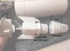
Here are the v3 parts. I've adjusted measurements about 1-2mm for each part. All parts are just put in place - not cemented yet.

I raised the front neck piece a couple of mm so the m577 piece sits at a good height against the droid socket.

The droid socket was widened a little so the jack piece and m577 pieces could sit beside the droid. You'll notice that the shell welder hexagonal piece barely fits. It's also placed kind of sloppily by me. The parts that sit behind the droid socket are sitting on a solid rectangular 3d printed bar. I added that because I didn't know how to manipulate the files well enough, but I could make an extra, solid piece they could sit on.

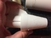
Overall, the top area works now. Not so with the bottom piece.

The bottom piece I widened so it would match up with the widened droid socket piece. So now it's too wide for the m577 vent and rectangular sealab parts. I had to also widen the slot where it sits on the aluminum armature, also because I couldn't manipulate the exterior surfaces separately.

The morgan part is also too wide for that part. It needs a channel to sit in, and that quad/25 pounder part at the sides of the morgan piece still won't fit well.

So that's the story: upper areas are ok, while widening the bottom piece didn't work out so well. It was pretty spot on in the first place. So there's a mismatch, potentially, between the upper and lower pieces. I don't know how that would be fixed as of now.

I also couldn't work on the wedge pieces that go on the bottom because they contain diagonal surfaces that I don't know how to manipulate in rhino. Dave can probably figure out all of this quicker. It's probably worth waiting for his mods.
 
Yes, I forgot to mention that I lowered the rearmost piece, so the orange sealab parts would be able to sit in there. The sealab parts are also sanded down to half their height too, I believe from ref pics.

Thanks for the update Scott. So did you have to lower the very rear of the the top of the neck where the orange/tube looking pieces (sorry don't know the part) meet up with the main fuselage? The reason being, I notice the top of the rear of the neck sits flush with the main fuselage on Dave's design and I'm pretty sure that crevice with the orange part should sit below the main fuselage.
 
Also, last night I noticed if you don't widen the neck, the long 8rad pieces on the sides and their angle will not fit properly against the main hull. Yes, I know my 8rad piece is facing the wrong direction. I just wanted to illustrate where it would meet up with the hull if the neck is not widened. According to my measurements the main hull width is correct so the neck not only needs to widen to fit the greeblies along the narrow ledge, but to fit the 8rad pieces correctly also.
20160912_0736502.jpg
 
Scott - You've done a Man's job, Sir! (okay, wrong franchise but you get the point).

The bottom part, what I call the Oil Pan, has angled sides which can be modified so that it meets up with the new width of the top but is still the correct width for the Sealab part on the bottom.

Hammer - You mention the length of the neck needs to be increased? Where and how much. There is a little bit of room for extension in the front before it'll interfere with the back of the forward fuselage. I'm pretty confident in the overall relationship between the forward fuselage and the main fuselage.

Scott, send me your V3 files and I'll se what I can do about modifying the master model. I am slammed trying to get all the fuselage castings out so please be patient.

Great work again!
 
Hey Dave.

I don't know how much. But the 25pdr piece on the back doesn’t work unless it's made longer. I'm not home so I don't have any reference with me.
 
Sorry to bring this up in Scotts excellent build thread but I have been asked if I can still cast the sealab parts for the Y-Wing. I still have molds so if anyone wants some just pm me.

I'll delete this if you like Scott.
 
Wow Julien! Thanks. I love when things like that happen. It definitely looks like a ship part.

The yellow part looks familiar to me too. Like a large part from a large kit. Almost like a jack part of a tank.

- - - Updated - - -

Ok. Two down...


I think the blue is the Bandai 1/48 King Tiger. The part numbers don't match but it looks close.


View attachment 665568

View attachment 665569

Here's 41. its missing the hole though.
 
Last edited:
I'm searching for some parts that are unique to the Ladd right side wing/fuselage area. If we can ID these parts, then guys building this version will be able to complete it pretty well.

I have ID'd one of the parts so far. Any help would be appreciated. If anyone has castings available, I'd like to buy them. Thanks in advance.

Could this be the possible yellow part?
s-l1600.jpg
 
Not so sure about this one. I think it might be easy to scratch this one if it doesn't show up though.

Sorry I was so late responding. I fell off the project for a while. You've got a great eye for the parts Ron!

I think the blue is the Bandai 1/48 King Tiger. The part numbers don't match but it looks close.


View attachment 665568

View attachment 665569

Here's 41. its missing the hole though.
 
I have some questions about the parts shown in the attached jpg. For anyone who's reached this point on their projects.

First: I think I've seen that the correct height for the part on the left is to cut it to 11mm.

Second: The cone on the right doesn't seem to fit over the core cylinder, and seems to need cutting down. I don't know how far. Has anyone gotten past this point? And I don't see a line that's on the Y on the cone piece. It should go around the circumference of the part.

Thanks in advance for any help!
 

Attachments

  • Engine parts questions.jpg
    Engine parts questions.jpg
    4.1 MB · Views: 363
Your LEM shroud needs the ring that it sits on, then trim it from there. I don't know the measurement, I just eyeballed it so I can't give you a correct answer.
 
I have some questions about the parts shown in the attached jpg. For anyone who's reached this point on their projects.

First: I think I've seen that the correct height for the part on the left is to cut it to 11mm.

Second: The cone on the right doesn't seem to fit over the core cylinder, and seems to need cutting down. I don't know how far. Has anyone gotten past this point? And I don't see a line that's on the Y on the cone piece. It should go around the circumference of the part.

Thanks in advance for any help!
i know the Saturn 5 parts, what are the other pieces, are they called out on any map? A lot of the structural pieces are missing from the maps
 
That's still debatable, however one thread showed a truck or trailer rim possibly being the part the heatsink sits in.

Edit. Sorry. I thought you were wondering if they were found parts.
 
Last edited:
i know the Saturn 5 parts, what are the other pieces, are they called out on any map? A lot of the structural pieces are missing from the maps

They're 3D printed parts that a member (can't remember the name right now) here made. The parts are available with Dave G's parts on his download site.
 
Last edited:
Just an FYI, if you used Stephan's files for the fins they are too long. The whole assembly only goes in so far before it rests on the cores. I needed to make new shorter ones so the nozzles didn't stick too far out of the back.

20161014_102823.jpg20161014_102033.jpg
 
Last edited:
This thread is more than 6 years old.

Your message may be considered spam for the following reasons:

  1. This thread hasn't been active in some time. A new post in this thread might not contribute constructively to this discussion after so long.
If you wish to reply despite these issues, check the box below before replying.
Be aware that malicious compliance may result in more severe penalties.
Back
Top