Progress!!! My back hurts from sitting in my office chair, but hey that's what the chiropractor is for.
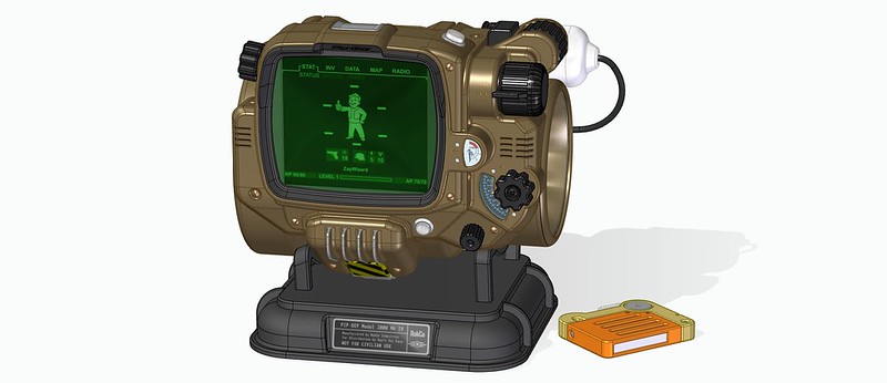
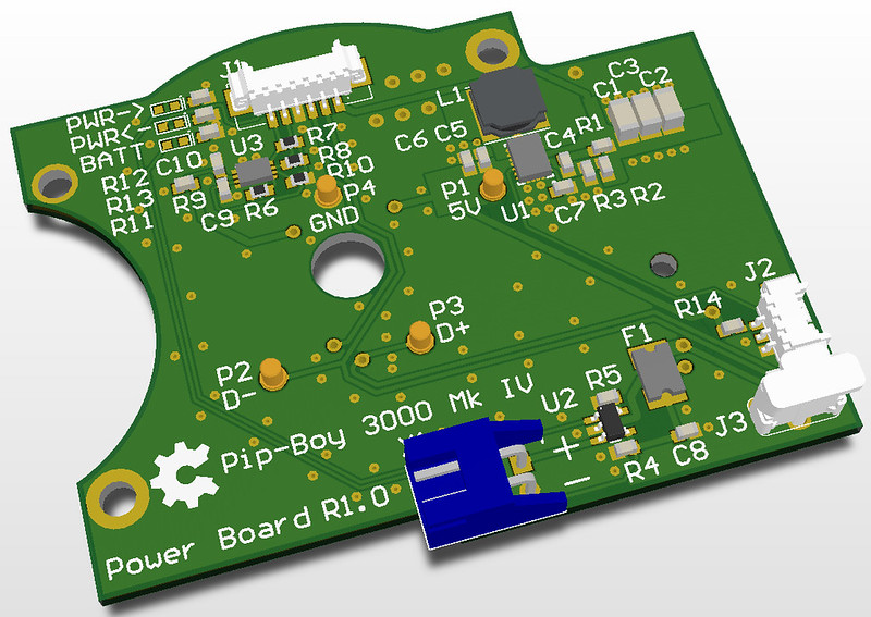
Above is the arbitrary overview image. There are so many tiny tweaks for the design, you could have to play spot the differences with an old image. Lets just say this is at least 95% game accurate now. I tweaked lots of small curves, added the odd less rounded corner near the light button, etc...
---------------
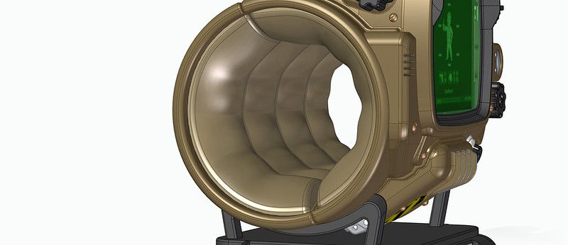
Here is the new game-accurate foam 3D model. Do you have any idea how difficult is it to 3D model this type of shape in a parametric program? It required lots and lots of 3D lofting functions. The foam is only about 3-6mm thick, placed over a plastic substrate which will act as a mount and stiff backer.
---------------
It is what is behind that foam that is exciting! I am finally getting around to doing those electronics I keep talking about. Seriously, my college education was all electronics, I just been doing mechanical engineering for the past fifteen years. (Granted all for stuff with electronics inside)
Inside the back is a 3.7V 1Ah LIthium Ion battery. I don't know how long that will last exactly yet, but it is really all the space I can spare. I also removed the odd "hidden" cord from the inside as it wasn't actually hidden enough. For now it will be a battery powered device, with external power available only via the link cable.
The link cable will connect to the charging dock I designed two years ago... (Damn this project is taking a while)
---------------
I am designing the printed circuit boards using CircuitMaker. I actually own a copy of Eagle Maker Edition, but I really finding that Eagle is stuck in the past. I really don't like the way it handles components and libraries, as well as cross-linking between PCB and Schematic. I was spending way too much time building very simple components.
Aslo CircuitMaker also has these cool 3D previews.
And all the source file will be public.
I did find their 3D export function to be totally neutered, so I will build up the boards inside SolidEdge later.
---------------
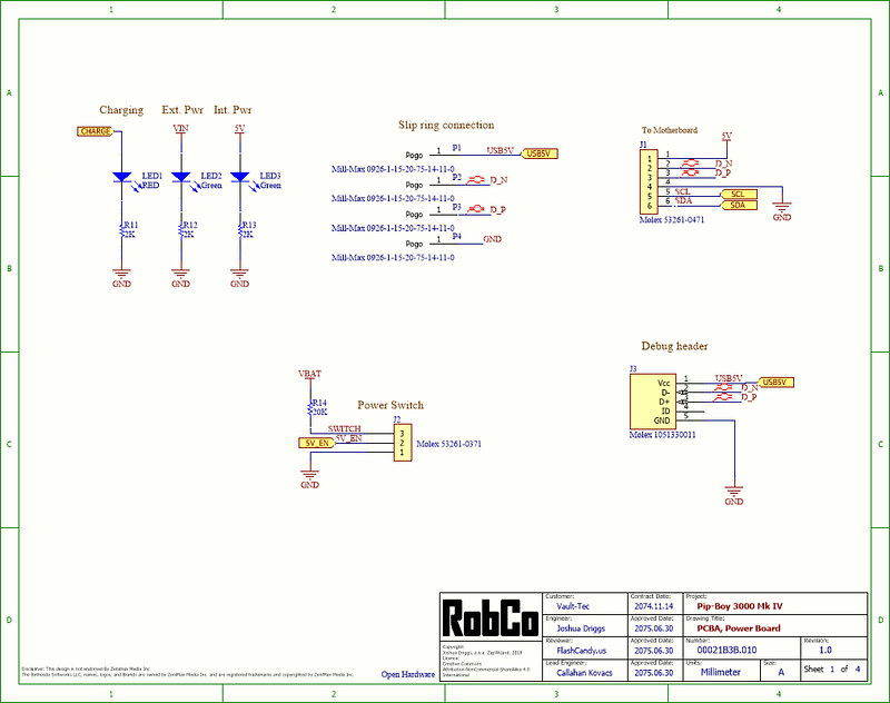
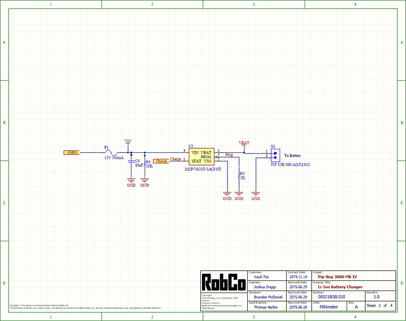
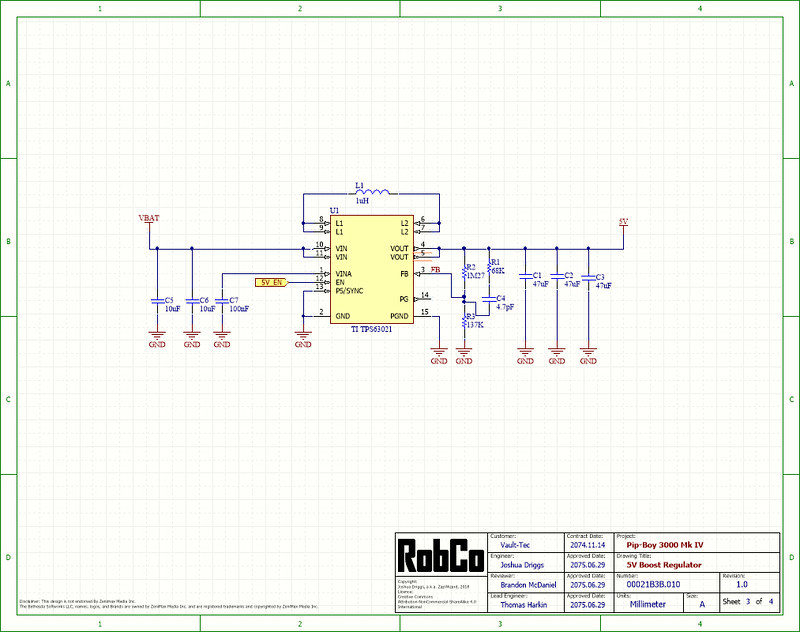
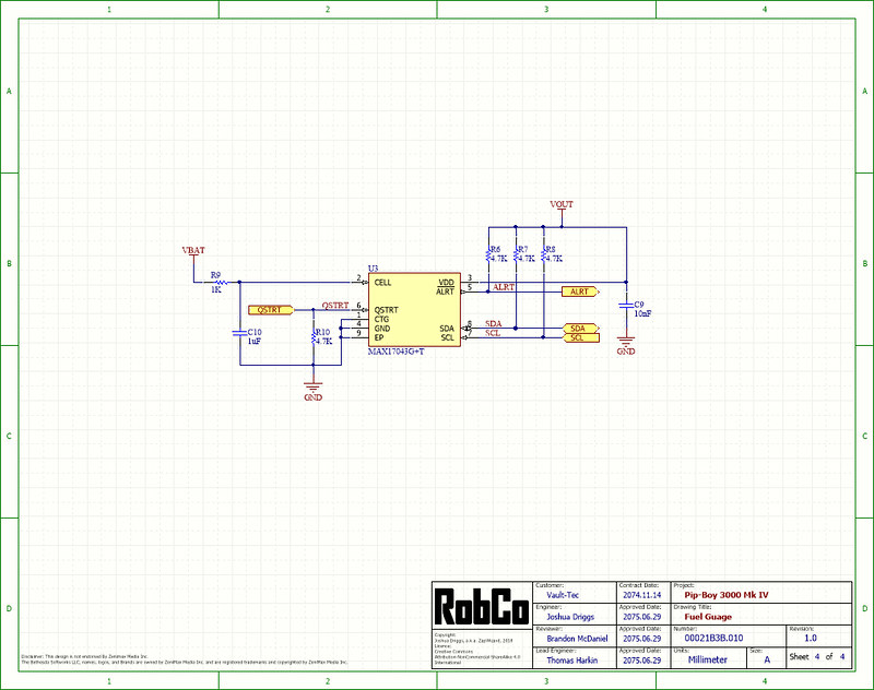
These four sheets make up the schematic for the above "Power Board". (Note the lore-friendly title blocks)
The board consists of a battery charger, a 5V boost regulator, and a battery fuel gauge. Along with the pogo-pins that link up to the slip-ring, which then links up to the link cable.
Most of the schematic blocks were taken from other open-source projects available on CircuitMaker. And most of these are really just re-creations of reference designs from the various chip makers.
---------------
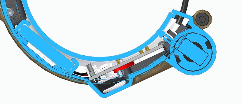
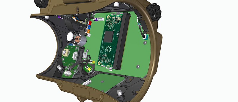
Many people think because the Pip-Boy looks so bulky, there must be lots of space inside.
But as this cutaway image shows, I have very little space in the back-half. Even the tiny pogo pins will still have to have clearance holes cut into the foam support bracket. If you look at that three pin connect near the middle of the image, it has a pitch of just 1.25mm.
---------------
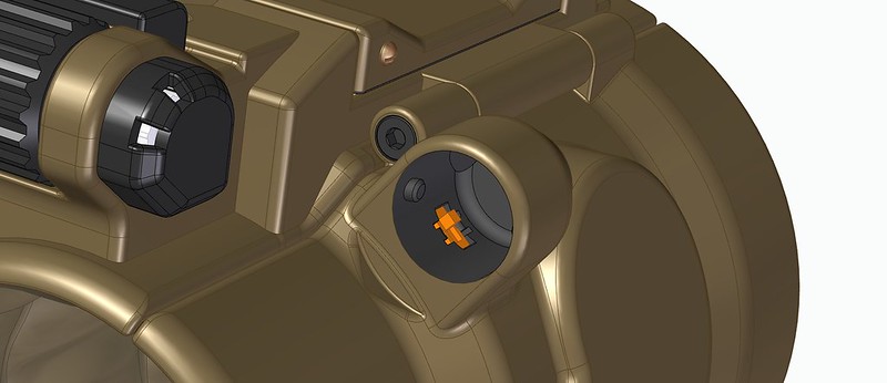
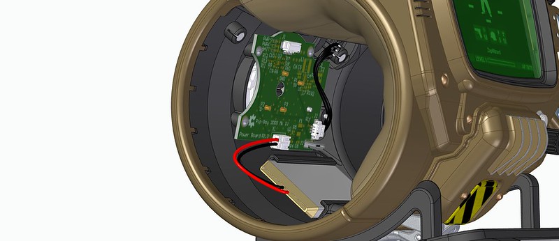
That little three pin connector will be wired to a hidden toggle switch inside the retainer for the link cable.
This will be the power-off switch to save battery. The "Power button" on the front will instead be wired up via software and simulate a power-up like you see in-game. It will sort of work more like a standby switch.
---------------
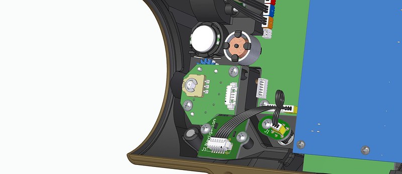
The front-half has also received lots of updates. I switched from the small square board-mounted speaker to a pre-wired round speaker. By separating it from the PCB allowed me to do some other tweaks that had been bothering me.
The rad meter actuator has moved to the motherboard. This makes it clear of the inside padding. (Before it was protruding a little bit.) This change means I will have to dremel the shaft to length. All these changes also means the radio knob is connected via a six pin cable, instead of requiring a large header.
---------------
More on the electronics:
I am debating swapping to a Raspberry Pi Zero W to the main board. (I know, I think this is the fourth time I have changed the main processor board.)
The DragonBoard 410c is turning out to have few issues that are giving me a headache.
1) It requires 8V to operate. There are hacks to make it work off of 3.3V or 5V, but both have limitations.
2) I am not sure it will actually be able to drive the 1920x1200 screen resolution. (It may be limited to 720p, or 1080p)
3) It was designed to be low-power, but relative to a larger computer. On battery it won't last very long.
I am also now looking at adding a SPI-to-DSI/MIPI frame buffer chip. What it would do is make it so the host process no longer has to be something super-fast, or even capable of driving a normal display. Instead, images would be sent to the frame buffer in a serial fashion. Sort of like writing a file to a SD card. This would be slower, but the Pip-Boy never had a fast interface anyways.
Another option it to use a DPI-to-DSI (Parallel to serial) convertor chip. This can be used since the Pi is actually capable of driving a DSI display natively.
Both boards can drive HDMI outputs. However before you say: "Here I found this HDMI screen you might be able to use" All of those use large convertor boards to go from HDMI to DPI,DSI,MIPI, or LVDS. They just won't fit inside.
")