Mr Fusion Base Progress

formula388

Well-Known Member
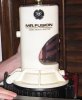
After reading about some peoples experiences about finding a bttf Mr. Fusion base, I am attempting to recreate it in CAD, then get it 3D printed. Though I do have access to a 3D printer, materials are expensive, even for me.
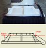
So far, after finding great information posted by several members (many of the information leads back to Gary Weaver posts) I have been able to create a CAD drawing of the white upper base mainly from Gary Weavers dimensions and my estimating. I uploaded it to shapeways and they want, just for the white base, $720. The printer I have access to would cost around $200-$250 in materials plus some time.
As with many of my projects, I am looking for input from members about how it looks, what can be changed to make it more screen accurate and possibly any other information to help along the way. My goal for this post is to try and create the most accurate white base as possible without actually having one in hand to copy from.
Since there is such a large cost in printing one of these, I am going to wait until I have the consensus of BTTF fans (and hopefully experts) before hitting the print button...

As for the black Singer Librascope bottom, I do plan on drawing it and getting it 3D printed as well, but in order to do so, I would need to draw it, then split it up into 4 quadrants and print each quadrant individually. I am going to put that project on hold until the white base is complete.

Here are two current screen captures of what I have come up with so far. I am looking for feedback from people!!!! Please help!
fusionbaseupper5.PNG
fusionbaseupper6.PNG
If anyone wants any dimensions to verify stuff let me know.
Thanks again,
Dennis

Update: Printed pictures on page 3
 
Last edited:
Yeah I imagined that 3D printing these parts were not going to be cheap and why I wanted to Vac Form and laser cut the parts.

I have a guy that can draw these parts for me in some CAD program I can't use that will produce an STL file but he charges about $80/per hour to do so. I would be paying for the machining of the bucks anyway.
 
I normally charge about $35 an hour for CAD work and STL file creation ;) I have done some work for members here upon request.

Anyway, I have the STL for the file above and I will be 3D printing these despite the high cost. After 3D printing, it is possible to Vacuum form the parts though I am not sure that it is the best method to reproduce the bases. I am really looking forward to feedback to make these parts as accurate as possible.

My biggest concerns about this "upper" base is, the latching area, and the hinged part.
 
Well, I am going to throw my progress up here anyway...
I changed the rear hinges in the back to go up almost full height of where the ribs start at the top.
I also added a "block" in the front for the latch.
Fusion.PNG

Fusion2.PNG
 
Well, an update for anyone interested. Using Gary Weavers CAD files, I have updated my parts. Roland has also provided me with several reference pictures that I have been working from.

fusionbase1.PNG

fusionbase2.PNG

I think I am close to hitting the print button on my 3D printer and seeing how it looks, hopefully it comes out awesome. I am waiting for some agreement on its accuracy.
 
The way I would do a Vac Form of the white part of the base is to strip off all the greeblies and work off the round plate itself. You need to make this solid (best results) and why I suggested having it machined. The greeblies including the hinge parts are best added to the plate later and could be laser cut. If you used a material like ABS, you can Vac Form, laser cut and glue all the parts (say Weldon#3) with high success. You might have to layer up the greeblies to get the right thickness. If you went with 10~12mm perspex you might have to find another adhesive.
 
Here is the latch I have been drawing, based off of Gary Weaver dimensions, but with some modifications.
latch.PNG
The only part I think I am going to change is the bottom hinged area, I am not feeling the angles...
 
Here is a rendering of the two parts together.
I think they look pretty good. (I also seem to be talking to myself)
This is actually a lot fun to draw.
assembly render.PNG
 
Looks great so far. But there are two details I would change. Look at my picture:

mr-fusion-base-progress-mrfusion_changes.jpg-236788d1380309622
 

Attachments

  • mrfusion_changes.jpg
    mrfusion_changes.jpg
    23.8 KB · Views: 2,901
Roland, what is the source of your fusion lid? It looks like my old V1 lid from 2004 or so. It's been recast a few time over the years and seems to be what's most people have these days.

The rear hinges are closer to level with the top, so the 3d model is pretty close. The front does need to come up to level. I'll try to post some details here in a bit.

The bottom of the red latch definitely needs correction. It's supposed to be a bent metal plate. Again, I'll post pics in a bit to help clarify it.
 
Alrighty, here we go.


Part I Fusion - ILM Reference Photo

ilm5-sm.jpg

You can see the rear hinge tabs are level with the coned top. Also the front is higher and level. This pic is one of the few pics that shows the lever latch intact. The story told to me is that Lloyd broke it on the first take and that's why it's missing from the film footage. All you see is a black pivot pin. That missing lever corresponded to the block you see on the front of the lid. The bent metal tabbed over it and held the latch in place when closed.

mr-fusion-base-bttf1.jpg

This shot also shows the bent metal latch hinge and how it bows out before it returns to the hinge block.
 

Attachments

  • IMG_0523-1.jpg
    IMG_0523-1.jpg
    64.4 KB · Views: 275
Gotcha - That's most probably one of the Videobob recasts of my V1 kit. You can tell by the gimpy aluminum plate "latch". The owner of the car used in that photoshoot/video is the guy who supplied Videobob with one of my kits to recast in the first place. Yippee....
 
Gotcha - That's most probably one of the Videobob recasts of my V1 kit. You can tell by the gimpy aluminum plate "latch". The owner of the car used in that photoshoot/video is the guy who supplied Videobob with one of my kits to recast in the first place. Yippee....

Gotta love the watering down of good work...


On another note, the vacforming idea is a good one and would be the most cost effective way to reproduce it. If you plan to go that route you will have to mod the master to allow for the thickness of the plastic if you want it to be dead on. Then just backfill the pull with foam or another suitable filler for stability and you are off to the races!
 
Gary, your 3 attachments of you early latch arent working. I think I understand what you are talking about with the bent metal, I havent yet drawn the second part of the latch, aka the latching mechanism.
Other then that, I will bring the front part of the base up.
I personally dont plan on vac forming these by the way.
Thanks for all the help guys.
 
Should the front come up all the way as seen here?
fusionbaseside.PNG
I have added the bent metal latch part as well, though I think the angle needs some tweaking in order to get it to actually work...
I would love to start printing some of these parts, though more screen grabs might be needed to verify accuracy. (I really need to learn how to do HD screen grabs from my digital copy.)
assembly render2.PNG
 
This thread is more than 5 years old.

Your message may be considered spam for the following reasons:

  1. This thread hasn't been active in some time. A new post in this thread might not contribute constructively to this discussion after so long.
If you wish to reply despite these issues, check the box below before replying.
Be aware that malicious compliance may result in more severe penalties.
Back
Top