robinhood jw
Member
I discovered Warehouse 13 after it was recommended by some friends and I saw that it was created by Jane Espenson (who wrote for Buffy and Firefly). I love the mixed historical eras of the props and equipment they use in the show. Once I got to season 2 and Warehouse 12 was mentioned (set in Victorian London), it got my imagination rolling.
See ... I'm a big fan of steampunk and have been to the Denver area steampunk con the last two years.
I decided I wanted to make a Tesla pistol that might have been carried by Warehouse 12 agents.
I started by drawing it up on CAD as close to scale as I could. The limiting factor was the plastic vial I was planning to use to substitute for the vacuum tube. (The vial originally held home brewing yeast.) I found some photos online that were pretty much a straight-on side view and scaled them up and down until the tube in the photo matched the size of my vial. Then I traced it in CAD and printed it out full size.
Once I had measurements for the various components I would need, I bought materials. Some of this I already had: the plastic vials, the walnut wood, the copper pipe coupler, the switch, the brass sheet, flat head brass screws. I bought a sheet of aluminum on ebay and I got the washers, brass rod, nuts, bolts, and the flashlight at Lowe's
I was starting to have an idea in my head of how it would go together, but I also knew I wanted to do some Victorian flourishes to give it a vintage aesthetic.
I hand drew on tracing paper over my CAD printout to work out how I wanted the shape to vary from the WH13 version and where I wanted the flourishes to be.
I adjusted some proportions to fit my hand better, and then cut out some templates from card stock.
Unfortunately, I didn't take many photos of the early part of the process. I traced the templates onto some walnut wood for the handles, cut them out and shaped them with a dremel and some hand filing. I traced the frame template onto aluminum and brass. In order to make the whole frame from brass, I was would have needed to buy a very pricey piece of 1/4" brass plate, which I really couldn't afford. Instead the frame is a sandwich of two thinner layers of brass with 1/8" aluminum in between. Aluminum turns out to be a lot tougher to cut than I expected. I killed a bunch of blades on my jeweler's saw cutting that thing out. Not to mention that aluminum sticks in your files badly, and I kept having to stop and clean out my files. I drilled and cut the side holes into the copper pipe coupler for the middle part. The thumb trigger is a brass pipe fitting tee. Some of the other pieces are held in place with rubber bands to check for fit.
I free-handed the flourishes onto the brass with pencil and then scribed them in with an awl. I heated the brass pieces with a propane torch to discolor it. The window cuts in the copper cylinder were filed down smooth and sanded and I drilled pilot holes for the "rivets". Then the copper cylinder was also torch-discressed. I trimmed down the brass tee for the thumb trigger, and cut the brass plates that will be the side panels in the copper cylinder.
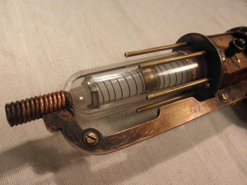
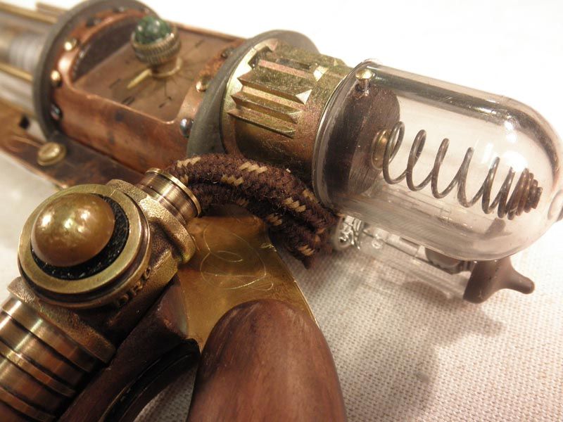
Here you can see the "vacuum tube" assembly mostly finished. The white tube inside is from the flashlight; wrapped with a spring and some old plumbing fittings. The piece of brass rod at the end of the tube is what the copper coil will wrap around You can also see some of the other parts coming together. The washer was drilled for the 6 brass rods. The ends of the copper cylinder have a wood disc for the various screws and parts to be mounted into.
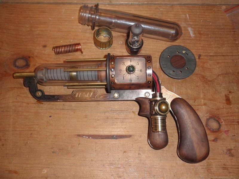
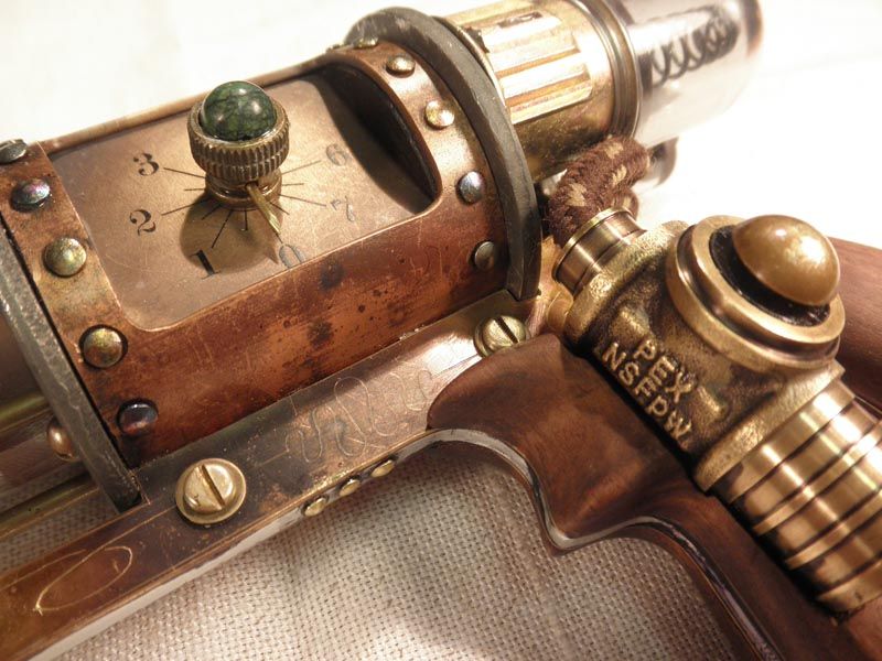
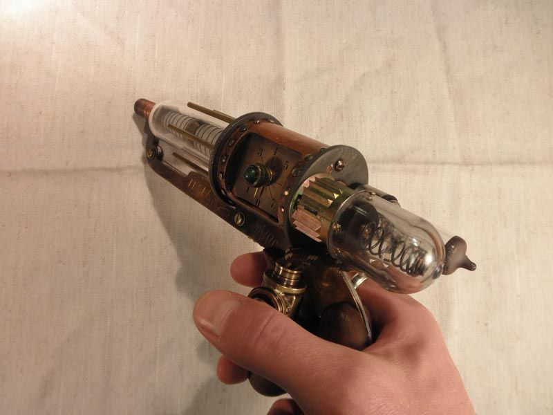
Here I've got the handles and the thumb trigger assembly mounted to the frame, the vacuum tube mounted to the main cylinder, and the dial assembly in place. I'd originally planned on having the trigger not only light up the vaccuum tube, but to make it buzz/vibrate also. I took the vibration motor out of an old cell phone and mounted it in part of the thumb trigger assembly. I ended up not using it because it ate through the batteries too fast. It's still there, but not wired up. That's why there's 4 wires coming out of the thumb trigger to the main part. The dial face was actually designed in photoshop and printed onto a clear address label and then stuck onto a piece of brass for the side panel. I created the knob out of part of an old hose sprayer, a nail, and a green stone bead. Sitting off to the side are some of the parts that aren't built or added yet.
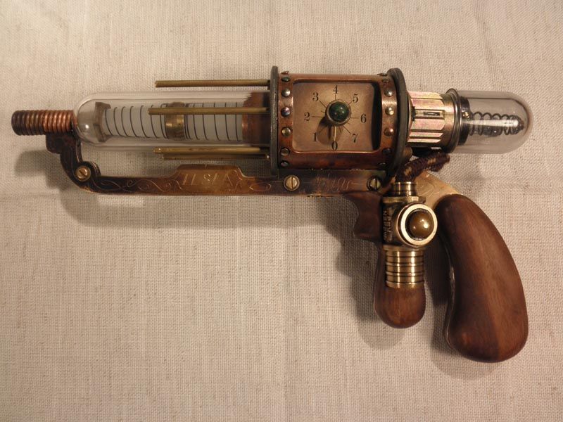
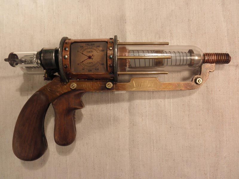
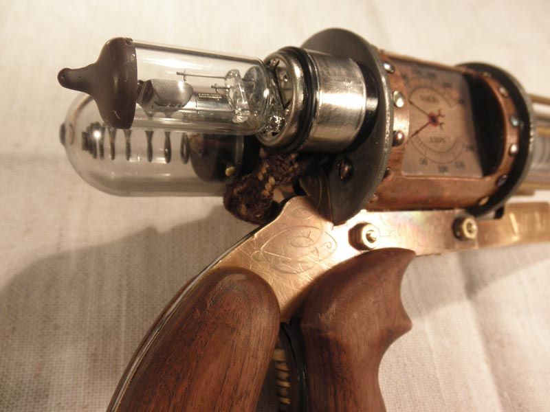
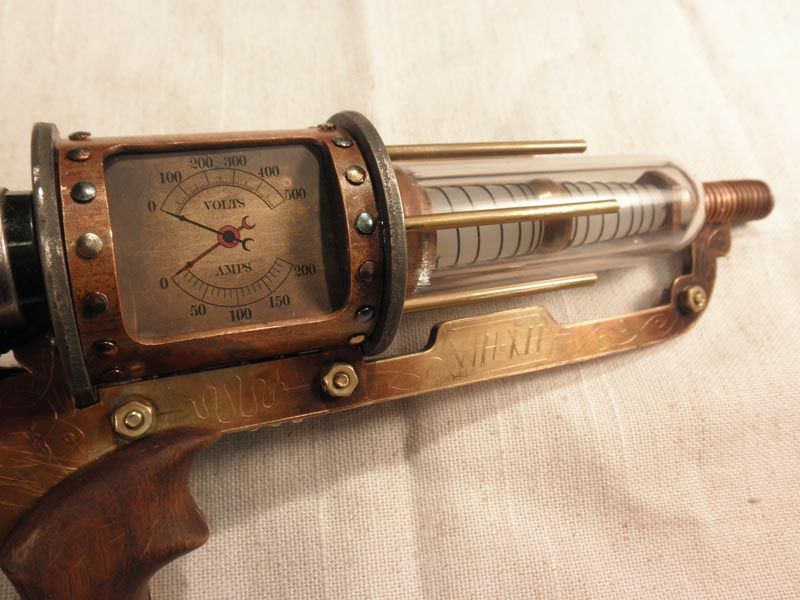
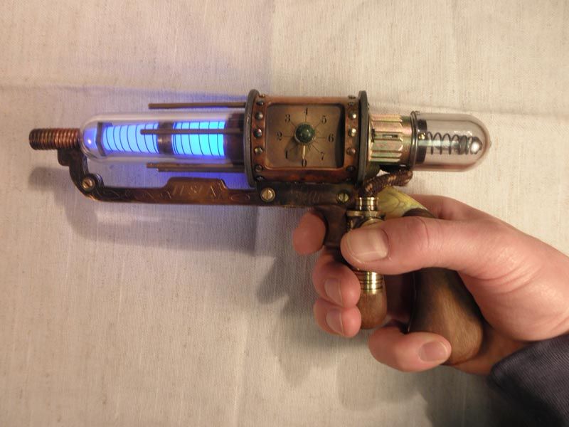
The final piece. I added the coil around the barrel and the rear-facing "vacuum tubes". One of these is from an old headlight from my car that I trimmed down. The other rear tube was made from another yeast vial, a spring, and part of an old door lock mechanism. Since the batteries are inside the main cylinder, the whole rear panel and both rear tubes can be removed. The wires are covered with an old shoe-lace (credit for this idea goes to an article on steampunk workshop). In spite of the fact that there's a LOT of epoxy holding this together, I tried to also mechanically fasten parts together wherever possible. I just don't quite trust the glue to hold up all on it's own. There are usually pins or screws in addition to the epoxy at most joints.
All in all, this was a fun project and I'm very happy with the result. I sometimes have to keep myself from wanting to do more distressing. (It looks good like it is, stop messing with it!) From beginning to end, it took about 2 months. Since a bunch of the components were things I already had lying around, I think my total cost for new parts was around $30-40.
Thanks for reading this looooooong post!
See ... I'm a big fan of steampunk and have been to the Denver area steampunk con the last two years.
I decided I wanted to make a Tesla pistol that might have been carried by Warehouse 12 agents.
I started by drawing it up on CAD as close to scale as I could. The limiting factor was the plastic vial I was planning to use to substitute for the vacuum tube. (The vial originally held home brewing yeast.) I found some photos online that were pretty much a straight-on side view and scaled them up and down until the tube in the photo matched the size of my vial. Then I traced it in CAD and printed it out full size.
Once I had measurements for the various components I would need, I bought materials. Some of this I already had: the plastic vials, the walnut wood, the copper pipe coupler, the switch, the brass sheet, flat head brass screws. I bought a sheet of aluminum on ebay and I got the washers, brass rod, nuts, bolts, and the flashlight at Lowe's
I was starting to have an idea in my head of how it would go together, but I also knew I wanted to do some Victorian flourishes to give it a vintage aesthetic.
I hand drew on tracing paper over my CAD printout to work out how I wanted the shape to vary from the WH13 version and where I wanted the flourishes to be.
I adjusted some proportions to fit my hand better, and then cut out some templates from card stock.
Unfortunately, I didn't take many photos of the early part of the process. I traced the templates onto some walnut wood for the handles, cut them out and shaped them with a dremel and some hand filing. I traced the frame template onto aluminum and brass. In order to make the whole frame from brass, I was would have needed to buy a very pricey piece of 1/4" brass plate, which I really couldn't afford. Instead the frame is a sandwich of two thinner layers of brass with 1/8" aluminum in between. Aluminum turns out to be a lot tougher to cut than I expected. I killed a bunch of blades on my jeweler's saw cutting that thing out. Not to mention that aluminum sticks in your files badly, and I kept having to stop and clean out my files. I drilled and cut the side holes into the copper pipe coupler for the middle part. The thumb trigger is a brass pipe fitting tee. Some of the other pieces are held in place with rubber bands to check for fit.
I free-handed the flourishes onto the brass with pencil and then scribed them in with an awl. I heated the brass pieces with a propane torch to discolor it. The window cuts in the copper cylinder were filed down smooth and sanded and I drilled pilot holes for the "rivets". Then the copper cylinder was also torch-discressed. I trimmed down the brass tee for the thumb trigger, and cut the brass plates that will be the side panels in the copper cylinder.
Here you can see the "vacuum tube" assembly mostly finished. The white tube inside is from the flashlight; wrapped with a spring and some old plumbing fittings. The piece of brass rod at the end of the tube is what the copper coil will wrap around You can also see some of the other parts coming together. The washer was drilled for the 6 brass rods. The ends of the copper cylinder have a wood disc for the various screws and parts to be mounted into.
Here I've got the handles and the thumb trigger assembly mounted to the frame, the vacuum tube mounted to the main cylinder, and the dial assembly in place. I'd originally planned on having the trigger not only light up the vaccuum tube, but to make it buzz/vibrate also. I took the vibration motor out of an old cell phone and mounted it in part of the thumb trigger assembly. I ended up not using it because it ate through the batteries too fast. It's still there, but not wired up. That's why there's 4 wires coming out of the thumb trigger to the main part. The dial face was actually designed in photoshop and printed onto a clear address label and then stuck onto a piece of brass for the side panel. I created the knob out of part of an old hose sprayer, a nail, and a green stone bead. Sitting off to the side are some of the parts that aren't built or added yet.
The final piece. I added the coil around the barrel and the rear-facing "vacuum tubes". One of these is from an old headlight from my car that I trimmed down. The other rear tube was made from another yeast vial, a spring, and part of an old door lock mechanism. Since the batteries are inside the main cylinder, the whole rear panel and both rear tubes can be removed. The wires are covered with an old shoe-lace (credit for this idea goes to an article on steampunk workshop). In spite of the fact that there's a LOT of epoxy holding this together, I tried to also mechanically fasten parts together wherever possible. I just don't quite trust the glue to hold up all on it's own. There are usually pins or screws in addition to the epoxy at most joints.
All in all, this was a fun project and I'm very happy with the result. I sometimes have to keep myself from wanting to do more distressing. (It looks good like it is, stop messing with it!) From beginning to end, it took about 2 months. Since a bunch of the components were things I already had lying around, I think my total cost for new parts was around $30-40.
Thanks for reading this looooooong post!

")