How about a new rendering.
-----------------------
I may not end up modifying the original Philco radio. The front of it is curved in such a away that getting the faceplate to fit perfectly will be very difficult. I would also have to color match the insert panel and I am not confident that I can do that to my satisfaction.
So I have updated my CAD design to be a game-accurate shape. The in-game design has the darn knobs pushed way towards the sides, when I would rather have them centered inside their cutouts. Fortunately the insert panel can be swapped out if I decide to deviate on that detail.
/Update: I can push the knobs to the nicer centered position. My friend pointed out they are centered in Fallout 3.
-----------------------
The construction will be built the same as the Philco radio with a plywood base, and wooden sides, top and back. I have not yet decided if I will make it from real wood, or try to do a water transfer print over MDF.
The Philco radio has a "Photo finish", and I can't find any documentation on how they actually applied it. The finish wraps around the entire radio, it is possible they used a water transfer method.
It seems obvious to just use real wood, however the end-grain may cause issues due to the curved edges. I have found a water transfer sheet which is a near perfect match for the grain and tone of the in-game radio.
Regardless of which method I do, I have to decide between trying to CNC carve the wood, or use a tall bandsaw to try to get close to the required curves. I know I don't want to sand the whole thing down to shape.
-----------------------
The back panel will have an On/Off switch, a special spiral power cord grip I designed, USB-Micro jack, and a composite video output.
The USB and Composite video will allow me to debug the Pi Zero without having to take everything apart. With some code changes the USB could also be used to expand the Pi storage using an external disk. The composite video could perhaps do some karaoke video feature. I figured having analog composite video out instead of HDMI would be more in the Fallout style.
-----------------------
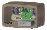
All the parts except for the power supply will mount to a single PCB. The Pi Zero and Pi Pico both will be mounted on headers to allow swapping them out if needed. The air core motor sits in the middle, and the buttons, motor driver and i2s speaker amps will all be housed on the PCB.
Everything then mounts to the faceplate.
-----------------------
I have already 3D printed a prototype of the faceplate. It is printed on a Form Labs Fuse 1. The Fuse 1 is an SLS 3D printer which means it can print almost any geometry without worrying about overhangs. The parts are ready to use once you clean off the powder.
-----------------------
Here it is mounted to my test mock-up. The Radiation King logo was printed a while ago, and was colored with a Molotow Chrome pen. The gauge face is currently just a laser etched black acrylic panel with the paper layer left in place. It will be a acid etched brass plate in the final form.
-----------------------
I also received my Ultrasonic microphone PCB design. It works! Except that CircuitPython's PDM in code has a bug. The bug makes the sample rate fixed at 22.1KHz per channel instead of being variable. I will still go ahead and put the microphone into the design and hope that the software can be updated later to make the mechanical remote work.
-----------------------
Code wise: I have done lots of updates. I now have the Pi Pico connected to the Pi Zero using a single USB connection, with no secondary UART needed. With the Pico connected to the Zero, you only have to load code onto the Zero. The zero then mounts and copies the required code over to the Pi Pico. This makes updating both sets of code much easier. The only catch is they way Linux handles a USB interruption, which means if the Pico is reset you have to reboot the whole thing. I have tried a bunch of re-mounting code, but it never restores the USB storage, and USB UART consistently.
The Zero and Pico also now talk to each other and each has a heartbeat signal to ensure that if one crashes, the other code goes into standby.
Attachments
Last edited:
")
