You are using an out of date browser. It may not display this or other websites correctly.
You should upgrade or use an alternative browser.
You should upgrade or use an alternative browser.
Yavin 4 scanner (ANH) - all major parts positively identified
- Thread starter 3DImpact
- Start date
After the initial flurry of activity and excitement with the discovery of the identity of the scanner parts I've been spending the last couple weeks tinkering with and refining the finer points of the assembly. I thought I'd share a bit more background and what I've learned in the process.
First off, just a bit more detail on the Arriflex motors themselves. There are two types that you'll commonly see, the constant-speed governed 24 fps and the variable-speed.

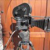
The variable-speed seems to be the one that comes 'standard' with the Arriflex II and serves double duty as the main hand grip. I've seen many photos of the constant-speed motor used with the camera mounted on a tripod with the motor attached to a flatbase adapter next to the camera. The Arri used on location at Tikal would have been used this way.


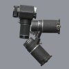
The 'discovery' comparison image that I showed in the first post was made with an assembly that used two of the variable-speed motors and represented my initial 'best guess' at how the scanner might have been assembled. If you look critically at that image and my higher-res version in post #16, though, you'll note that compared to the screencap reference the top portion of the Minolta spot meter sits a bit 'flat' with respect to the top motor. More specifically, I assembled that first version assuming that the plane passing horizontally through the central 'equator' of the Minolta was aligned parallel to the central axis of the top Arri motor. Taping two variable-speed motors together at their plug ports results in a very natural and obvious positioning for the Minolta with a straight up-and-down handle and a flat, horizontal top, so that was a natural first guess. Looking carefully at the Minolta in the on-screen version you'll see that the 'equator' of the Minolta is actually tipped up several degrees relative to the top of the top motor. I now understand why that is - it's the natural result of using a constant-speed motor in the assembly. There would have been at least one constant-speed motor on location at Tikal but I do not yet definitively know the actual motor combination they used for the scanner, only that two variable-speed motors do not seem to produce the correct look. So for now I am going on the assumption that they had one of each type of motor on hand - a variable-speed that came 'standard' with their Arriflex and a constant-speed that was used when the camera was mounted on a tripod. In Photoshopped 'cartoon' form this is what that assembly looks like without the tape so you can see why that naturally gives rise to the up-tilted Minolta seen on screen (and it does work and produce the same Minolta tilt if you swap the two motors around and two constant-speed motors seems to work just about as well also).

Knowing now that the scanner prop was assembled for temporary use from working parts that had to be returned to service, I have assumed the governing principle that neither motor nor the Minolta could be altered in any (permanent) way in the process. The two metal prongs in the motor plug ports do unscrew, but it is possible to join the two motors at the ports with the prongs in place, and in fact the prongs themselves actually help make for a more firm mate as they slide past and in contact with each other.

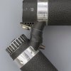
A few wraps of gaffer's tape around the mated plug ports and the motors are rather surprisingly firmly joined to each other.

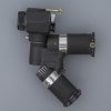
A few more wraps of gaffer's tape secures the Minolta in position (more or less - it wants to roll a bit but not so much as to be considered a 'fragile' connection).

I've also refined the mystery greeblie that ressembles a precision screwdriver taped to the top of the Minolta. Its appearance is now consistent across all the screencaps I've compared to.


You'll note in web searches for images of the motors that they do not have the prominent light-colored band near the plug port as seen on screen. I'm assuming for now that the crew dressed those up a bit with some tape to make for a bit more interesting color contrast on screen (otherwise the entire scanner would have been nothing more than a dark and boring silhouette). For my initial proof-of-concept assemblies I used aluminum tape as that seemed like a natural match to the existing narrow metal band on the motors. After a couple more photo shoots for comparison with the screencaps though, I've now settled on a light gray vinyl tape similar to electrical tape - the aluminum tape is a bit too specularly reflective. I do not know what tape they might have actually used on location (if it even was tape) but the light gray vinyl tape does match the on-screen appearance rather nicely.


Dan
First off, just a bit more detail on the Arriflex motors themselves. There are two types that you'll commonly see, the constant-speed governed 24 fps and the variable-speed.

The variable-speed seems to be the one that comes 'standard' with the Arriflex II and serves double duty as the main hand grip. I've seen many photos of the constant-speed motor used with the camera mounted on a tripod with the motor attached to a flatbase adapter next to the camera. The Arri used on location at Tikal would have been used this way.


The 'discovery' comparison image that I showed in the first post was made with an assembly that used two of the variable-speed motors and represented my initial 'best guess' at how the scanner might have been assembled. If you look critically at that image and my higher-res version in post #16, though, you'll note that compared to the screencap reference the top portion of the Minolta spot meter sits a bit 'flat' with respect to the top motor. More specifically, I assembled that first version assuming that the plane passing horizontally through the central 'equator' of the Minolta was aligned parallel to the central axis of the top Arri motor. Taping two variable-speed motors together at their plug ports results in a very natural and obvious positioning for the Minolta with a straight up-and-down handle and a flat, horizontal top, so that was a natural first guess. Looking carefully at the Minolta in the on-screen version you'll see that the 'equator' of the Minolta is actually tipped up several degrees relative to the top of the top motor. I now understand why that is - it's the natural result of using a constant-speed motor in the assembly. There would have been at least one constant-speed motor on location at Tikal but I do not yet definitively know the actual motor combination they used for the scanner, only that two variable-speed motors do not seem to produce the correct look. So for now I am going on the assumption that they had one of each type of motor on hand - a variable-speed that came 'standard' with their Arriflex and a constant-speed that was used when the camera was mounted on a tripod. In Photoshopped 'cartoon' form this is what that assembly looks like without the tape so you can see why that naturally gives rise to the up-tilted Minolta seen on screen (and it does work and produce the same Minolta tilt if you swap the two motors around and two constant-speed motors seems to work just about as well also).

Knowing now that the scanner prop was assembled for temporary use from working parts that had to be returned to service, I have assumed the governing principle that neither motor nor the Minolta could be altered in any (permanent) way in the process. The two metal prongs in the motor plug ports do unscrew, but it is possible to join the two motors at the ports with the prongs in place, and in fact the prongs themselves actually help make for a more firm mate as they slide past and in contact with each other.

A few wraps of gaffer's tape around the mated plug ports and the motors are rather surprisingly firmly joined to each other.

A few more wraps of gaffer's tape secures the Minolta in position (more or less - it wants to roll a bit but not so much as to be considered a 'fragile' connection).

I've also refined the mystery greeblie that ressembles a precision screwdriver taped to the top of the Minolta. Its appearance is now consistent across all the screencaps I've compared to.


You'll note in web searches for images of the motors that they do not have the prominent light-colored band near the plug port as seen on screen. I'm assuming for now that the crew dressed those up a bit with some tape to make for a bit more interesting color contrast on screen (otherwise the entire scanner would have been nothing more than a dark and boring silhouette). For my initial proof-of-concept assemblies I used aluminum tape as that seemed like a natural match to the existing narrow metal band on the motors. After a couple more photo shoots for comparison with the screencaps though, I've now settled on a light gray vinyl tape similar to electrical tape - the aluminum tape is a bit too specularly reflective. I do not know what tape they might have actually used on location (if it even was tape) but the light gray vinyl tape does match the on-screen appearance rather nicely.


Dan
Last edited:
Thanks for those images demonstrating the assembly. I was trying to picture it in my head, and I couldn't do it!
I'm not even gonna try to hunt the parts for this prop! It's really neat, and you've done top notch work figuring it out, though.
Also, they do make grey gaff tape, so maybe that's indeed what was used.
EDIT: I realize it could be a long shot, but I've got this pin vise that looks similar to the top greeblie. The 15.9mm on the caliper is the width of the hexagonal head. The larger diameter of the main body is 9mm and the length is roughly 90mm.

ANOTHER EDIT: Of course now that I look back at those most recent images, it looks less and less like this is what it could be. So, heh, forget what I just said!
I'm not even gonna try to hunt the parts for this prop! It's really neat, and you've done top notch work figuring it out, though.
Also, they do make grey gaff tape, so maybe that's indeed what was used.
EDIT: I realize it could be a long shot, but I've got this pin vise that looks similar to the top greeblie. The 15.9mm on the caliper is the width of the hexagonal head. The larger diameter of the main body is 9mm and the length is roughly 90mm.
ANOTHER EDIT: Of course now that I look back at those most recent images, it looks less and less like this is what it could be. So, heh, forget what I just said!
Last edited:
ANOTHER EDIT: Of course now that I look back at those most recent images, it looks less and less like this is what it could be. So, heh, forget what I just said!
No, this is good - this is how we'll figure this out eventually! I still have hopes that at some point Edlund or Peterson may be able to provide some further insights with memories perhaps refreshed by all this...
Dan
3DImpact:
Thanks for sharing this discovery!
Great detective work.
Looking forward to Jerry's replica.
I can testify that the motors are heavy: in college I used an Arri BL (16mm) and there were two motors: one that was variable and the other that was a crystal sync version (24fps) so you could record audio on the Nagra reel to reel. If the two weren't running at the exact same speed, your audio would be off.
Again, Awesome Work!
Last edited by a moderator:
Looking good! Glad they made it safely.
I am green with envy looking at this lot John
Marv
Sr Member
Thank you again for forwarding on to me the arri partsLooking good! Glad they made it safely.
Thank you again for forwarding on to me the arri parts
Which you will forward to ME now, riiiight
Wow, now THAT brings back memories! My dad used to have that exact set! I remember the little base and that clear plastic cover. That's so cool, I haven't thought about that in a loooooong time.I just picked up a vintage multi tool screwdriver sets, to see how it looks, the bit on top is somewhat thinner than most.
View attachment 849485
Sent from my VS996 using Tapatalk
trooper
Sr Member
sorry for the delay in getting these done. but I finally have the molds for the motors done.
I have some screws and some small bits to get tomorrow, but I will be casting these up for any one who wants them
the two motors with the top greeblie for the spot 1 is $225 + shipping
I will run thread in the JY, but your more than welcome to preorder if you like, just pm me


I have some screws and some small bits to get tomorrow, but I will be casting these up for any one who wants them
the two motors with the top greeblie for the spot 1 is $225 + shipping
I will run thread in the JY, but your more than welcome to preorder if you like, just pm me


Last edited:
Similar threads
- Replies
- 22
- Views
- 5,232
- Replies
- 33
- Views
- 5,773
- Replies
- 39
- Views
- 12,071
- Replies
- 94
- Views
- 17,200
- Replies
- 57
- Views
- 44,801


