Y-Wing (Gold Leader) Build - Nice-N Model Designs

It looks like there shouldn't be any more major changes to be made with the parts, so
I took the time this week to start cleaning all of the parts, starting with the larger ones (Just warm water and dish detergeant).

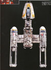
With those parts cleaned and dried, I reassembled the large parts and started fitting them with the aluminum, inner structure. If any more machining needs to be done at this point to the aluminum structure, it has to be done now because according to the instructions, the aluminum can simply be glued to the resin.

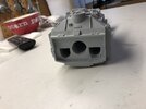
Considering the size and weight of this model, not to mention the fact that this isn't exactly a low priced project, I decided it might be wise to bolt the engines to the flat aluminum bar with four wood bolts, so I mark the ends of the aluminum piece in four spots for the bolts. This is the port side:

IMG_2022.JPG

And starboard:

IMG_2023.JPG

At this point I realize that there is no "holder" for the engine light for the port side, which basically sucks, but I'll figure out some thing later.

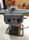
If I'm drilling holes, might as well drill two more so that the center bar is attached to the flat bar, so I mark two holes for it:

IMG_2024.JPG

Four holes marked for the port side:
IMG_2022.JPG

and for the starboard side:
IMG_2023.JPG

Holes marked and centered on the rod:
IMG_2024.JPG

All holes drilled and then counter sunk:

IMG_2026.JPG
 
Last edited:
The tube is drilled and tapped for the two, 4-40 bolts:

IMG_2027.JPG

Might as well mark the holes on the engines:
IMG_2028.JPG

Starboard side:
IMG_2030.JPG

Since the engines are resin, I just use some basic, wood screws.
Here's every thing assembled, top side:

IMG_2032.JPG

And the bottom:
IMG_2031.JPG

So it's progressing. The next step will be to fit the front piece to make sure that the tube is the proper length, etc.
 
Before moving on to the forward fuselage, I did some more sculpting work with these guys:

IMG_2040.JPG

I've added the "step" to each piece and did a general cleanup after hitting them with their first coat of primer. They could need several coats before they're ready for final assembly.

I wanted to make sure that the aluminum tube was installed properly, so I check fit the rear panel:

IMG_2043.JPG

It fits flush, so we're good:

IMG_2044.JPG

Moving on to the forward fuselage, I remove the forward section and test fit it to the forward piece. The notch doesn't appear to be long enough, but I need to check the rest of the pieces before modifying anything:
IMG_2041.JPG

The tube is a good length. It just touches the "box" area. I'm not sure if the end of the rod is suppose to connect to something here or not. More on this later:

IMG_2042.JPG

I realize that there is one more, large piece that actually fits between the forward fuselage and the main body. According to the directions, to install it correctly, a hole needs to be drilled near the center. I use a step drill bit to make the hole. It's the largest drill bit I have:

IMG_2045.JPG

I test fit the part and clean it a bit with a x-acto knife. The instructions specify that some detail may need to be removed from the center of the part for the main section to fit flush with the part. I use a variety of x-acto knives to remove the detail:

IMG_2046.JPG

I doesn't fit perfectly on the forward section, but some clamps should hold it in place once it's ready for some glue:

IMG_2048.JPG
 
It's easier just to use rubber bands at this point to keep all of the larger pieces together and to save some space:

IMG_2049.JPG

Here's a shot of the neck detail:

IMG_2050.JPG

Up next, machining tubes for the engines, finishing up the engine details, attaching the forward section and installing the wiring.
 
Looking great! However I'm struggling to understand why your upper and lower fuses were that different in length? I know parts were removed from the Red Jammer and parts added to make the Gold Leader, but that still shouldn't matter.

One thing if you're striving for accuracy is that the back plate
FB_IMG_1472522345689.jpg
needs to be trimmed and mounted recessed like the original.

IMG_2044.JPG
 
Yes, I'll be adding that one to the list. ;)

I decided to take a break from the engine details and the main body by tackling the missing engine tail rings.
For whatever reason, these were not included in the kit, but I they did come with another kit I previously owned, so I wrote down the measurements and checked them against the other tail parts and the reference photos:

Engine Tail Rings.JPG

It looks like they got the measurements right. The outer diameter is 1.5" which looks about right when I place them on top of the corresponding parts. I thought that one of the other tubes used for this model might match the 1.5" diameter, but after checking the parts I realized that this just wasn't the case, so I checked my stock aluminum and other materials, but 1.5" just couldn't be found. I checked my box of prop parts and what I came across was an old, resin copy of a Tasco scope, which was exactly 1.5" in diameter. They were used at one point on the ROTJ Han Solo blasters. I'm really glad I kept it, although an aluminum version of the rings would have been nice to have. :)
 
Would love to see the specs on the Tasco scope id and od, and height, if you have a good micrometer/caliper.

I was under the impression that the rear ring came from the Bandai 1/16 Rolls-Royce Balloon Car inner rims, which mic out exactly as they should, and which ILM confirmed they had in the shop at the time of the making of the original Star Wars movie.
 
I am sure you are correct because the Tasso scope I have wasn’t used in ANH.

While working with the main sections, I realized that some extra material on the bottom section should probably be removed in order to prevent problems later when detailed parts need to be attached:

9BEBD88B-1217-41A0-8298-D80486452611.jpeg


C7FB2A0F-982D-4B2C-BA56-932CF4161E58.jpeg

I use the mill to quickly remove the extra material near the rear and middle sections:

7ED7C179-1B71-4B18-9960-F3167A716097.jpeg

I checked the forward section against some reference photos with the model details attached and it looks good, so the extra material in that area may have been by design. I also checked the rear and middle sections and they also look good at this point.
 
Last edited:
I discovered that the forward section of the bottom part has a "trench" for wires. Does any one know if this was for the power switch or to light the cockpit?

IMG_2074.JPG

Here's a reference photo of the original model (bottom of the cockpit area). Is this a toggle switch for the power?

InkedPower Switch_LI.jpg

The next step with the body is to drill top and bottom, mounting holes through the the resin pieces (9/16" drill bit) and the aluminum plate.
Once that's done, the aluminum tube needs to be drilled and tapped with a 1/4-20 tap:

IMG_2076.JPG

Before gluing the main parts together, I want to make sure that the rear section fits together properly (It's going to be a lot easier to make modifications while the two parts are separated). The tube was sticking out a bit, so I machined it down and cleaned it up. The bottom section is also sticking out, so I mark the areas in prep for milling them:

IMG_2077.JPG

The end mill couldn't reach the corners, so I finished them off with some x-acto knives:


IMG_2078.JPG

At first I thought that either the top or bottom section was cast an angle, but it turns out that the rear indentation isn't level, which may be true of the original model. Here's a different view of the rear area:

IMG_2079.JPG
 
Last edited:
There were no lights in the cockpit on the original models. The wires going to the cockpit were for when the model was mounted by the front mounting point.
I would think the toggle switch was for the main power.
 
There were no lights in the cockpit on the original models. The wires going to the cockpit were for when the model was mounted by the front mounting point.
I would think the toggle switch was for the main power.
Interesting, thanks! I thought that was a toggle switch. :)
 
The tube is drilled and tapped for the two, 4-40 bolts:

View attachment 1367381

Might as well mark the holes on the engines:
View attachment 1367382

Starboard side:
View attachment 1367383

Since the engines are resin, I just use some basic, wood screws.
Here's every thing assembled, top side:

View attachment 1367384

And the bottom:
View attachment 1367386

So it's progressing. The next step will be to fit the front piece to make sure that the tube is the proper length, etc.
Hi...are you sure you haven't reversed the top and the bottom ?
 

Attachments

  • TK Top.jpg
    TK Top.jpg
    6.4 MB · Views: 181
With the rear indentation now level, I am now ready to align the sides. The right side is definitely sticking out more:

5901BCC8-A66C-4807-91EC-4C55A34D0CCC.jpeg

I check the bottom and see that there’s no detail that will be removed if I modify this area so we're good:

406DC1C7-54F9-4055-AF4D-192E2871FDC3.jpeg

I use a belt sander and a square file to remove the extra material.

FC971EE0-0826-4A2D-90D0-01ADE851E85A.jpeg
 

Attachments

  • D3B8AA2C-ABF1-46CB-AE74-D954F54A515F.jpeg
    D3B8AA2C-ABF1-46CB-AE74-D954F54A515F.jpeg
    1.8 MB · Views: 145
  • 05311293-BF7D-4650-B8A3-54894B9DC8BB.jpeg
    05311293-BF7D-4650-B8A3-54894B9DC8BB.jpeg
    1.1 MB · Views: 163
Last edited:
Time to fit the rear hatch again. Looking at the reference photo, the hatch isn't attached to the frame and some of the detailing was removed to get it to fit, so after giving it some thought, I decided to stick with this design rather than use the practical approach, so I removed this section from the part, but kept some of the frame so it could be fitted to the rear area:


IMG_2083.JPG

I used the mill, a couple of x-acto knives and finally a belt sander to clean up the hatch.

Here it is, fitted in place with the frame:


IMG_2085.JPG

Looking at the reference photo, the frame isn't sticking out enough, so I'll need to attach and blend in the remaining frame part from the hatch:

IMG_2086.JPG

Since I still have the main sections apart, I might as well drill the holes for the hatch magnets. I have some small earth magnets left over from my SS TIE fighter wing "hatches", so I'll just use those:

IMG_2087.JPG

Up next, setting up the wiring before finally gluing the main sections together. :)
 
The original instructions never cover the wiring, so I'll do this step by step in case it's useful for future reference.

After giving it some thought, I decided to use a toggle switch near the bottom of the neck, just like the original. It will be easier to turn the model off and on as well as give the neck area some small detail.
To help distinguish between the red/white wires coming from the engine lights, I'm going to use orange wire which will go directly to the switch near the front of the model.
The positive side of the battery will be sticking out, so the switch wire will go through the other side and circle around to attach to that end of the battery holder. I used some tape to keep it in place:


IMG_2089.JPG

To keep the two wires (one is attached to the positive side of the battery/switch and the other is attached to the positive - red - switch/engine wires) together, I use a mill to spin them. A drill of any kind will also do the trick.

To help see where the engine wires are going, I've only attached the bottom portions of the wings:

IMG_2091.JPG

The engine wires are then pulled through the holes in the top section:

IMG_2093.JPG

A rear view of the wires:

IMG_2094.JPG

Top view with all the main parts in place:

IMG_2095.JPG

Rear view:

IMG_2096.JPG

Forward view:

IMG_2097.JPG

Up next, attaching the LEDs, soldering and clean up the wire lengths.
 
I start by stripping the ends of all the wires and then adding a little bit of solder to the end of each:

IMG_2099.JPG

Both negative engine wires (off white) get soldered to the battery holder negative end:

IMG_2100.JPG

Both positive engine wires (red) are soldered to one of the switch wires (orange). The other switch wire (orange) is soldered to the positive end of the battery holder:

IMG_2101.JPG

The wires are a mess and they're exposed, but this is good enough to test the setup and there's no rush get this done. Also, once the main parts are sealed with glue, it will be very difficult to move around and fix disconnected wires, so it's not a bad idea to test the lights, first.
So the next step is to attach the LEDs to the other end of the engine wires.

I was lucky enough to work with some Motorola technicians who taught me some LED wiring and soldering skills while working on my first R2 dome. I spent about a month's worth of lunch breaks soldering about 100 LEDs, so I know something about wiring up LEDs. :)

The rule of thumb with LEDs is that typically the longer wire is the positive and a resistor should be soldered to the positive to prevent the LED from drawing too much power from the battery, otherwise the LED could burn out (usually turning red and then black) or simply empty the battery within only a few hours or minutes. Some of the newer LEDs nowadays come with built in resistors.

As with the ends of the wires, a small amount of solder is added to the ends of the LEDs and resistors:

IMG_2102.JPG

I was planning to add a switch to the set up, but since it's still in transit I think we're good, so by just twisting the orange wires together, we get a circuit:

IMG_2103.JPG

I'm leaning a little toward using the large, white LEDs, since the original lights appear to have been white with clear plastic painted red. It might effect the final appearance, but we'll see. Oddly enough, these LEDs were originally intended for a Han in Carbonite panel.

The lights looks good, so I trim the orange wire going to the battery holder and cover the exposed, positive wires with some heat shrink tubing:

IMG_2104.JPG

The tubing gets hit with a heat gun and then the wires are glued in place behind the battery holder.

Coming up next, cleaning up the wires and getting all the parts glued together.
 
Last edited:
The wires directly attached to the battery holder are kept together with heat shrink (Right engine negative and switch positive). The remaining wires (Right engine and switch positive) are also kept together with heat shrink:

IMG_2105.JPG

With every thing in place, I test the LEDs again to make sure they are lighting up and we're good, so now we can finally glue the main parts together. The bottom wing parts need to be attached as well since they partially sit within a couple of indentations on the sides of the bottom of the main body.

I use some contact cement to glue the two, top parts to the bottom section, using some rubber bands to keep the forward section in place.

The rear section isn't sitting completely flat, so I use a couple of clamps to keep it in place:

IMG_2106.JPG

Up next, cleaning up the main body, attaching the wings and the details.
 
Last edited:
The magnets need to be glued and allowed to set over night, so I attach those, first. The magnets are sanded down on one side and then super glue is applied inside the holes:


IMG_2128.JPG

I'll wait at least 24 hours before attaching magnets to the panel, so the magnets on the body aren't pulled off in the process.

According to the directions, the next step is to fill in the center line completely around the body. I use standard modelers putty to fill in most of the gaps. I'm going to leave the large gap in the center alone for now because I'd like to try some new, modeling epoxy in that area only:

IMG_2129.JPG
 
FWIW I am working on a file of a complete NAcelle Leggs Egg to trapezoid. Hollow of course with structural supports inside and a battery compartment. Will be a single one-piece print so no SEAMS HURRAY!
 

Your message may be considered spam for the following reasons:

If you wish to reply despite these issues, check the box below before replying.
Be aware that malicious compliance may result in more severe penalties.
Back
Top